Vehicle and method of controlling driving force for the vehicle based on detected slip of the drive wheel

a technology of driving force and detection of slippage, which is applied in the direction of brake systems, instruments, tractors, etc., can solve the problems of inability to drive the vehicle, overheating or damage of devices, etc., and achieve the effect of simple configuration and effective slippage control

Inactive Publication Date: 2011-06-07
TOYOTA JIDOSHA KK
View PDF23 Cites 24 Cited by
  • Summary
  • Abstract
  • Description
  • Claims
  • Application Information

AI Technical Summary

Benefits of technology

[0006]In the vehicle and the control method of the vehicle, there would thus be a demand for enabling effective slip control by a simple configuration. In the vehicle and the control method of the vehicle, there would also be a demand for attaining slip control by multiple different mechanisms. In the vehicle and the control method of the vehicle, there would further be a demand for preventing slip-induced unstable driving of the vehicle and damages of devices involved in slip control for the vehicle.
[0018]The control method of the vehicle according to another aspect of the invention computes the estimated speed of the vehicle body as the estimated vehicle body speed by integration of the actual driving force actually used for driving the vehicle and the computed drive wheel angular acceleration computed from the driveshaft rotation speed as the rotation speed of the driveshaft. Occurrence or non-occurrence of the certain slip of the drive wheel is then detected, based on the rotation speed of the drive wheel expected from the estimated vehicle body speed and the computed drive wheel rotation speed computed from the driveshaft rotation speed. In response to detection of non-occurrence of the certain slip, the power source is controlled to output a driving force corresponding to a driving force demand required for driving and drive the vehicle with the output driving force. In response to detection of the occurrence of the certain slip, on the other hand, the power source is controlled to output a driving force corresponding to the driving force demand with drive restriction of the power source and drive the vehicle with the restricted output driving force. The control method of the vehicle in this aspect enables detection and control of the certain slip, based on only the actual driving force actually used for driving the vehicle and the driveshaft rotation speed. This arrangement enables effective slip control by the simple configuration. Here the actual driving force actually used for driving the vehicle and the driving force demand required for driving include both a driving force for acceleration and a braking force for deceleration.

Problems solved by technology

Another known technique for slip control of the drive wheels by a single mechanism requires some special measure, since there is a potential for some failure or abnormality arising in the single mechanism.
In one proposed structure of the vehicle having a function of allowing the driver to inactivate a slip controller, for example, with the driver's preference to the acceleration performance, the occurrence of a large slip in the inactive condition of the slip controller may cause troubles, such as unstable driving of the vehicle and overheat or damage of devices involved in the slip control for the vehicle.

Method used


Image

  • Vehicle and method of controlling driving force for the vehicle based on detected slip of the drive wheel
  • Vehicle and method of controlling driving force for the vehicle based on detected slip of the drive wheel
  • Vehicle and method of controlling driving force for the vehicle based on detected slip of the drive wheel

Examples


Embodiment Construction

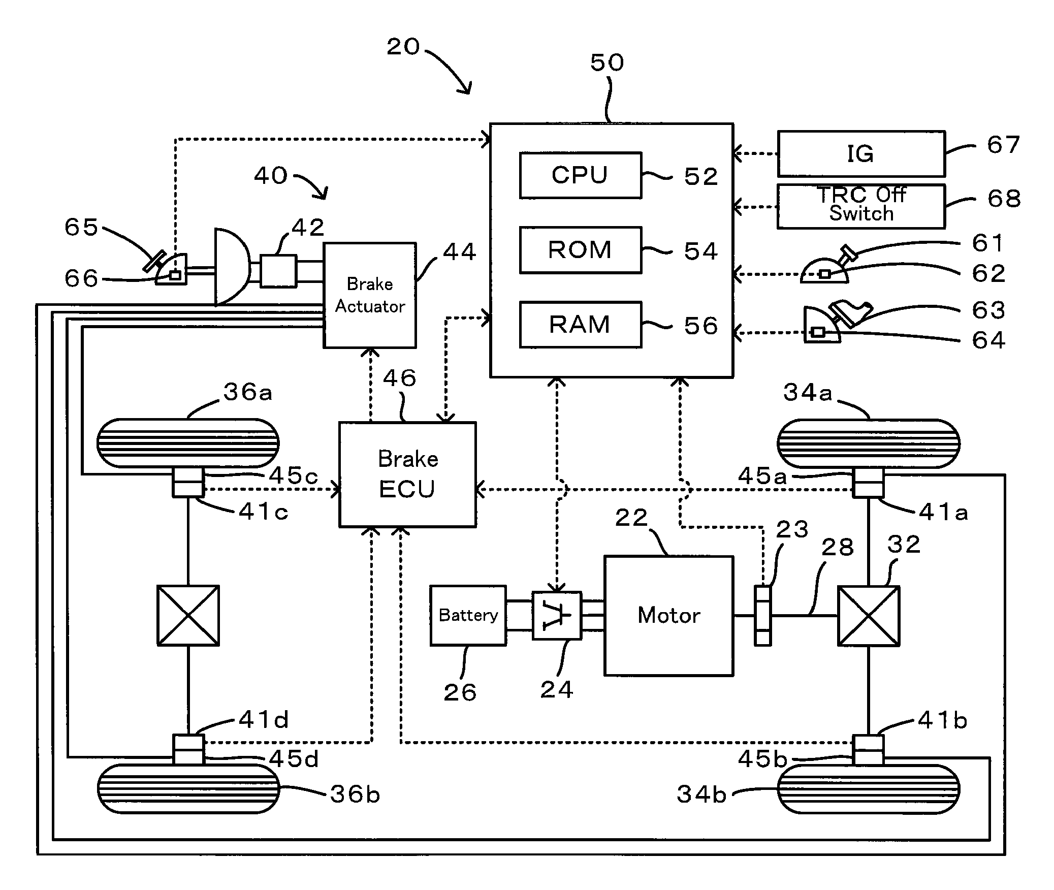
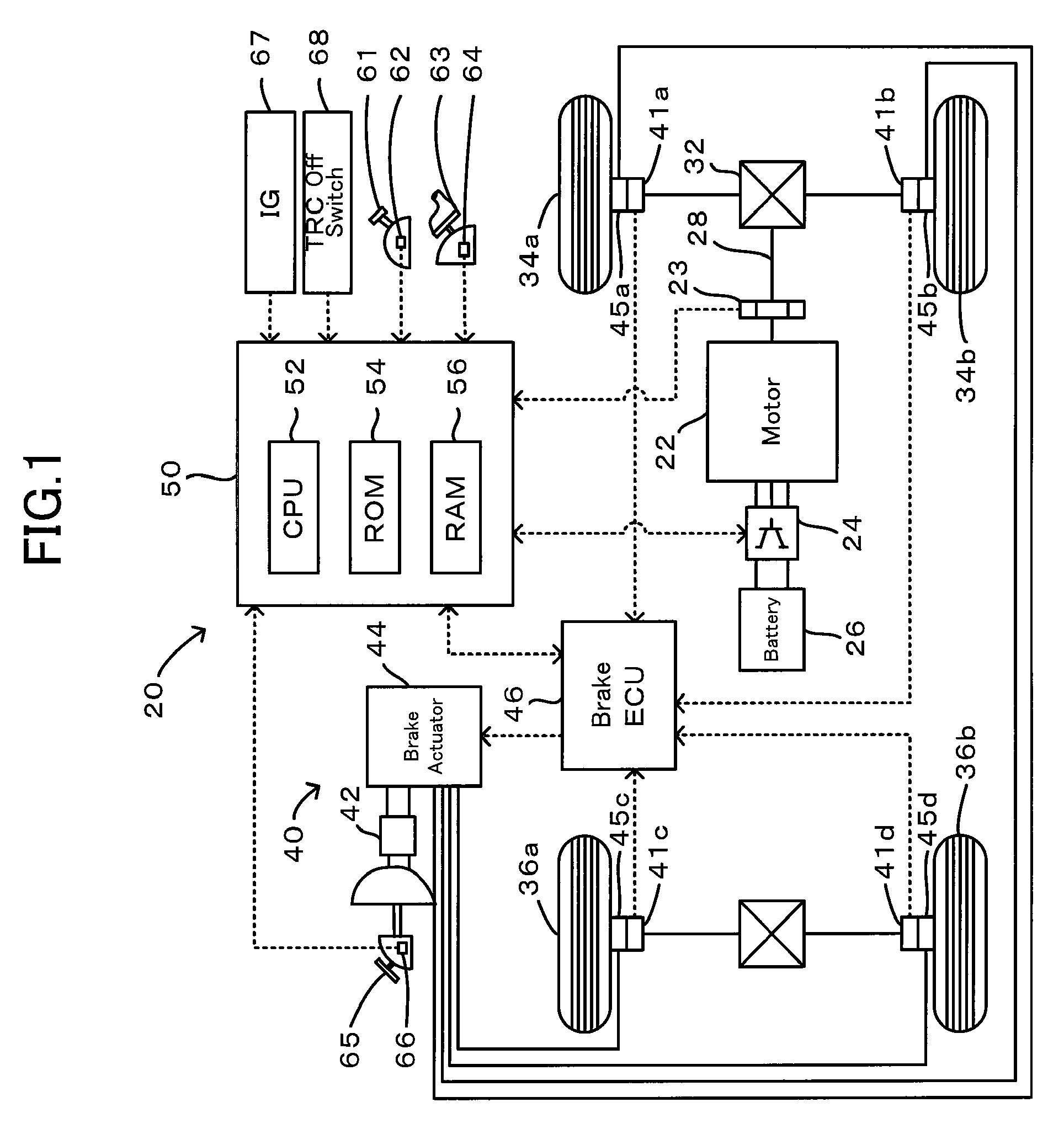
[0037]One mode of carrying out the invention is described below as a preferred embodiment with reference to the accompanied drawings. FIG. 1 schematically illustrates the configuration of an electric vehicle 20 in one embodiment according to the invention. As illustrated, the electric vehicle 20 of the embodiment has a motor 22 configured to input and output power from and to a driveshaft 28 linked with drive wheels 34a and 34b via a differential gear 32, a rotational position detection sensor 23 constructed to detect a rotational position of a rotor in the motor 22, a brake system 40 configured to apply a mechanical braking force onto the drive wheels 34a and 34b by a supply of hydraulic pressure from a brake actuator 44, and a main electronic control unit 50 configured to control the operations of the whole electric vehicle 20.

[0038]The motor 22 is constructed as a known synchronous motor generator to transmit electric power to and from a battery 26 via an inverter 24. The rotatio...


PUM


Abstract

The occurrence or non-occurrence of a certain slip of a drive wheel is detected based on only a motor torque used for driving a vehicle, a brake torque, and a rotation speed of a motor computed from an output of a rotational position detection sensor. In response to detection of the occurrence of the certain slip, drive restriction of the motor is activated for slip control. The slip control is attainable by a brake system and the drive restriction of the motor. Even in the event of any failure or abnormality arising in the brake system or in the event of prohibiting traction control of the brake system in response to the driver's operation of a TRC off switch, the drive restriction of the motor accomplishes the slip control. This arrangement desirably prevents slip-induced unstable driving of the vehicle and damages of devices involved in slip control for the vehicle.

Description

[0001]This is a 371 national phase application of PCT / JP2007 / 068932 filed 28 Sep. 2007, claiming priority to Japanese Patent Applications No. JP 2006-273168 filed 4 Oct. 2006, and No. JP 2007-169200 filed 27 Jun. 2007, the contents of which are incorporated herein by reference.TECHNICAL FIELD[0002]The present invention relates to a vehicle and a control method of the vehicle.BACKGROUND ART[0003]One proposed structure of a vehicle is equipped with at least one motor provided in a power source used to output driving power to drive wheels and with an integration controller configured to detect a slip of the drive wheels and perform torque reduction control of the motor (see, for example, Patent Document 1). In the vehicle of this prior art structure, the smaller between a slip amount-based torque limit value and an angular acceleration-based torque limit value to a motor torque limit value. The slip amount-based torque limit value is based on a slip amount computed from wheel speeds of...

Claims


Application Information

Patent Timeline
Patent Type & Authority Patents(United States)
IPC IPC(8): B60K28/16B60W40/10B60W40/12B60L9/18B60T8/175B60W10/04B60W10/08B60W10/18B60W10/184B60W30/00F02D29/02
CPCB60T8/175Y02T10/7258B60T2270/402Y02T10/72
Inventor ITOH, TAKAO
Owner TOYOTA JIDOSHA KK
Why Eureka
Try Eureka