
Placement of I/O blocks within I/O banks using an integer linear programming formulation

a technology of integer linear programming and i/o blocks, applied in the field of circuit design, can solve the problems of inability to place i/o rpms anywhere in the bank, inability to assign clock-io blocks to any site in the bank, and inability to implement i/os of these two i/o standards in the same i/o bank. achieve the effect of fast and efficien

Active Publication Date: 2011-06-07
XILINX INC
View PDF12 Cites 13 Cited by
  • Summary
  • Abstract
  • Description
  • Claims
  • Application Information

AI Technical Summary

Benefits of technology

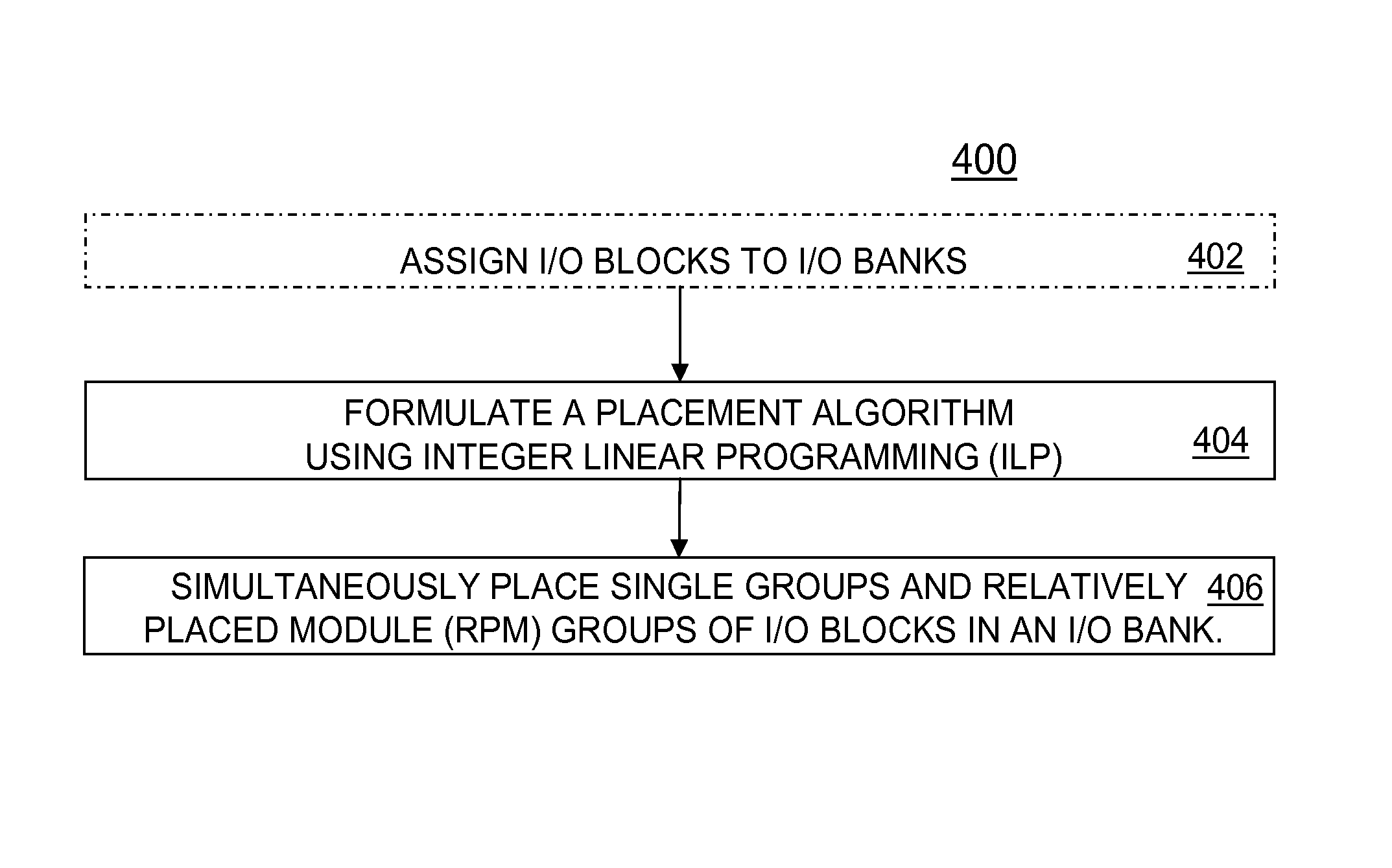
[0033]A generic approach for intra-bank placement or a method for placement of I / O blocks assigned to an I / O bank that is based on Integer Linear Programming (ILP) formulation is presented. This approach can automatically determine if a given problem instance is feasible or not. This approach treats both single IOs and IOs that are part of an RPM in a similar way and allows to use powerful and very efficient numerical methods developed for ILP solvers. The algorithm allows for quick and unambiguous detection of placement solution feasibility. The method can be very fast and efficient. The method can avoid ordering dependencies and allows for simultaneous placement of single and RPM groups of I / O blocks. The ILP formulation is described in more detail below and includes description of ILP variables, set of constraints and an optional objective function.

Problems solved by technology

I / O standards that require incompatible values for their electrical parameters are said to be incompatible with each other and vice versa.
Since the Vcco values do not match, a circuit cannot implement I / Os of these two I / O standards in the same I / O bank.
However, if the single I / O blocks are placed such that no two adjacent sites are available (B), then the I / O RPM cannot be placed anywhere in the bank.
However, if all 10 of the non-Clock-IO blocks are placed onto the 10 Clock-IO sites in the bank, then the Clock-IO blocks cannot be assigned to any sites in the bank.
However if the 5 unconstrained I / O blocks are placed on the left-hand-side of the bank (D), then the range-constrained I / O block cannot be placed on any I / O site in the bank leading to an I / O placement failure.
As FPGA designs increase in complexity, they reach a point at which the designer cannot deal with the entire design at the gate level.
Nonetheless, physical placement within I / O banks is still a non-trivial problem because some sites may not be available for usage by some I / O blocks.
It is also much more complicated when the set of assigned I / O blocks are part of Relatively Placed Modules (RPMs).
Its main drawback is the very strong dependency on the ordering.
In a difficult situation, it frequently assigns some I / O blocks to the first available and compatible sites, while leaving some other I / O blocks without sufficient and suitable I / O sites.
It is also extremely difficult to use in situations when there are non-uniform sets of I / O blocks (e.g., clock IOs and regular Select IOs) that have different compatibility to available sites.
This method is much better for many situations, but it has a lot of inconsistencies when applied to a mix of single IOs and IOs that are part of RPMs.
As a result, for such situations, the method convergence is bad and results are not reliable.
Also note, it is a common feature of all heuristic approaches that they cannot prove the existence of a feasible placement solution or the lack of it.

Method used


Image

  • Placement of I/O blocks within I/O banks using an integer linear programming formulation
  • Placement of I/O blocks within I/O banks using an integer linear programming formulation
  • Placement of I/O blocks within I/O banks using an integer linear programming formulation

Examples


Embodiment Construction

[0040]Embodiments of the present invention are applicable to a variety of integrated circuits (ICs). Some embodiments have been found to be particularly applicable to and beneficial for programmable logic devices (PLDs). Explanations and descriptions of various embodiments of the present invention are illuminated by way of specific examples utilizing PLDs such as field programmable gate arrays (FPGAs). However, the present invention is not limited by these examples, and can be applied to virtually any IC that includes programmable resources.

[0041]Referring to FIGS. 3 and 4, flow charts illustrating methods 300 and 400 respectively of input / output (I / O) block placement assigned to an input / output bank are shown. As noted above and from a broader perspective, the generic Select IO placement problem can be divided into 2 separated tasks, namely, the assignment of all I / O blocks to available I / O banks (shown as optional step 402) and the sequential placement that creates a mapping betwe...


PUM


Abstract

A method of input / output (I / O) block placement assigned to an input / output bank includes formulating a placement algorithm using integer linear programming (ILP) and simultaneously placing single groups and Relatively Placed Module (RPM) groups of I / O blocks in the I / O bank. The method further includes determining a placeability matrix P and a binary assignment matrix X used for the ILP. The method can further eliminate all assignment matrix elements of X equal to 0 in the integer linear programming and re-index any remaining elements. The method can further place all I / O blocks according to a solution if solving of the standard ILP formulation results in a feasible solution. Optionally, the method generates a placement solution that is as close as possible to an external reference solution specified by designer. Optionally, the method analyzes which constraints were violated and generates useful error information.

Description

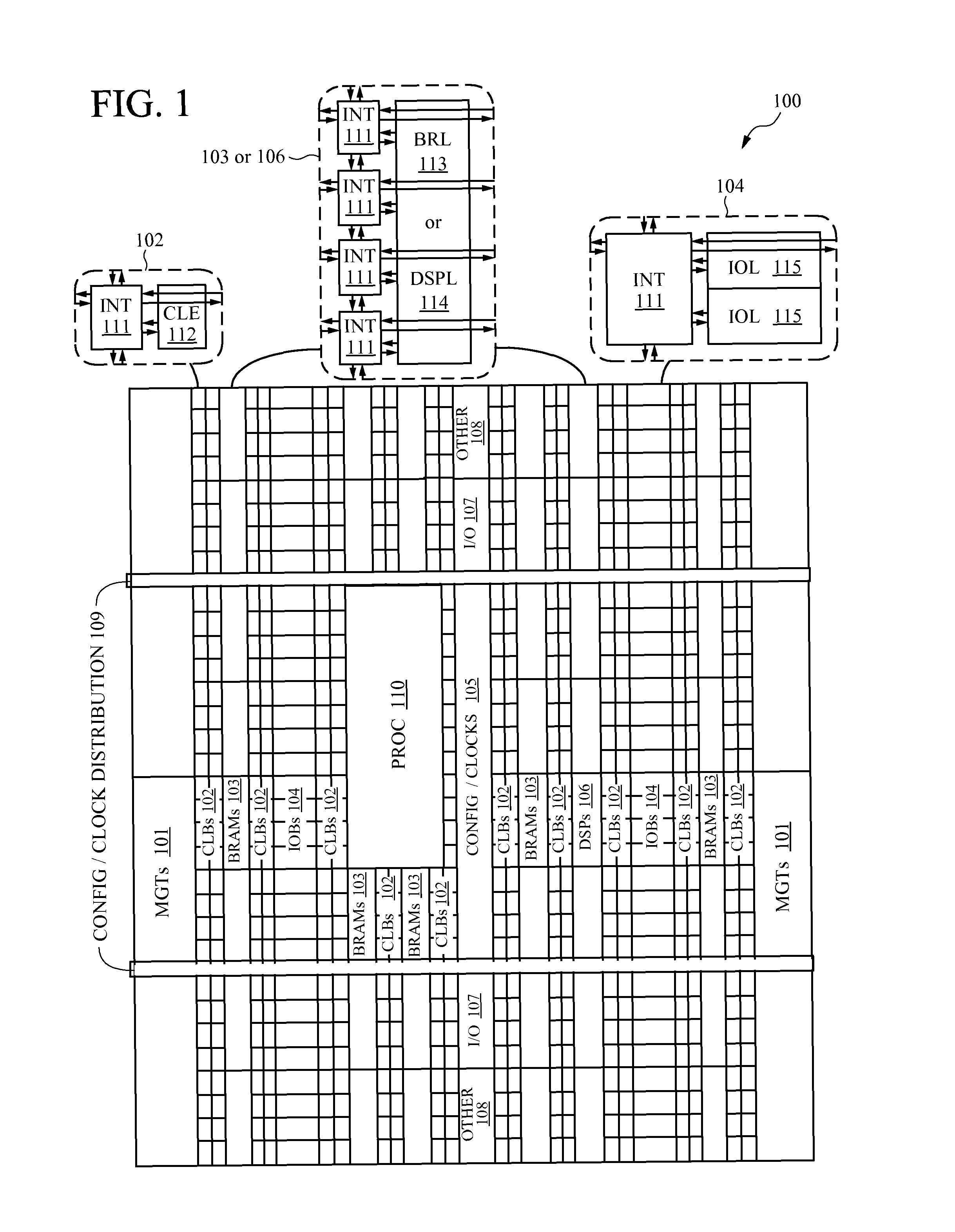
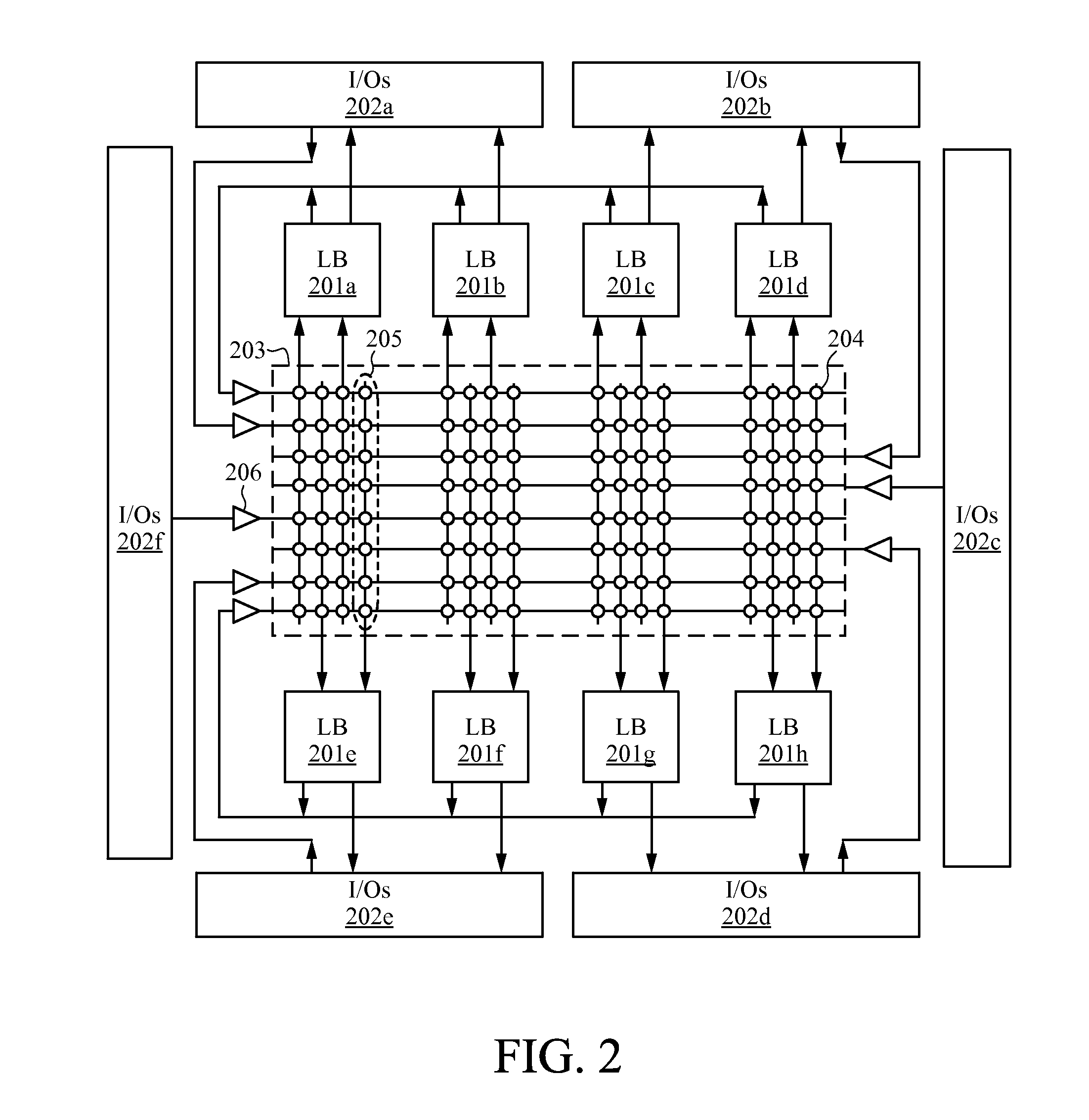
FIELD OF THE INVENTION[0001]The invention relates to the field of circuit design and, more particularly, to the use of Integer Linear Programming for placing the input / output (IO) components for a given design.BACKGROUND OF THE INVENTION[0002]Programmable logic devices (PLDs) are a well-known type of integrated circuit that can be programmed to perform specified logic functions. One type of PLD, the field programmable gate array (FPGA), typically includes an array of programmable tiles. These programmable tiles can include, for example, input / output blocks (IOBs), configurable logic blocks (CLBs), dedicated random access memory blocks (BRAM), multipliers, digital signal processing blocks (DSPs), processors, clock managers, delay lock loops (DLLs), and so forth.[0003]All PLDs including FPGAs, provide special programmable circuits that can be used as external inputs or outputs for a circuit design implemented on the device. These are collectively referred to as I / O Sites (or I / O pins)...

Claims


Application Information

Patent Timeline
Patent Type & Authority Patents(United States)
IPC IPC(8): G06F17/50
CPCG06F17/5072G06F30/392
Inventor SLONIM, VICTOR Z.KANNAN, PARIVALLALSTENZ, GUENTER
Owner XILINX INC
Learn More