Assembly of a shaft and a housing assembly

a technology of shaft and housing, which is applied in the direction of elastic bearings, couplings, slip-proof couplings, etc., can solve the problems of surface damage and particle generation of tolerance rings, damage to bearings,

Active Publication Date: 2011-06-14
SAINT GOBAIN PERFORMANCE PLASTICS RENCOL
View PDF25 Cites 19 Cited by
  • Summary
  • Abstract
  • Description
  • Claims
  • Application Information

AI Technical Summary

Benefits of technology

[0012]At its most general, the present invention proposes a method of assembling an apparatus from a pre-assembly, the pre-assembly comprising a first mating component that has a surface with a varying radius, a second mating component, and a band of resilient material located between the two mating components with an uncompressed projection extending therefrom. An interference fit is created between the components by rotating the first mating component to align the projection of the band of resilient material with a part of the surface of the first mating component which has a radius sufficient to compress the projection. This method of assembly minimises dragging of the first component along the band of resilient material, and subsequent surface damage to the first component.
[0027]The first part of the shaft surface has increased radial clearance between the band and the shaft, in comparison to the second part of the shaft surface, and consequently the method of assembly of the present invention avoids axial dragging of the shaft along the band of resilient material. Therefore, minimal effort is required to axially align all of the shaft, the housing and the band. The only significant force applied is a torque to finally align said projection of the band with the second part of the outer surface of the shaft, thereby performing a camming operation to compress said projection of the band.
[0028]The distance covered with said projection under compression for the assembly process is significantly reduced compared to conventional assembly methods, and so scraping of the surfaces of the mating components, i.e. the shaft or the housing, is minimised, which in turn minimises particle generation.
[0032]It will be appreciated that the same effect can be achieved with the housing having the surface with first and second parts, instead of the shaft, and the projections of the band extending radially outwards.

Problems solved by technology

For example, in hard disk drive pivot mounts the normal axial dragging of one component relative to the other mating component and the tolerance ring can give rise to surface damage and particle generation.
Also, in delicate bearing assemblies, such axial loading during assembly may damage the bearing.

Method used


Image

  • Assembly of a shaft and a housing assembly
  • Assembly of a shaft and a housing assembly
  • Assembly of a shaft and a housing assembly

Examples


Embodiment Construction

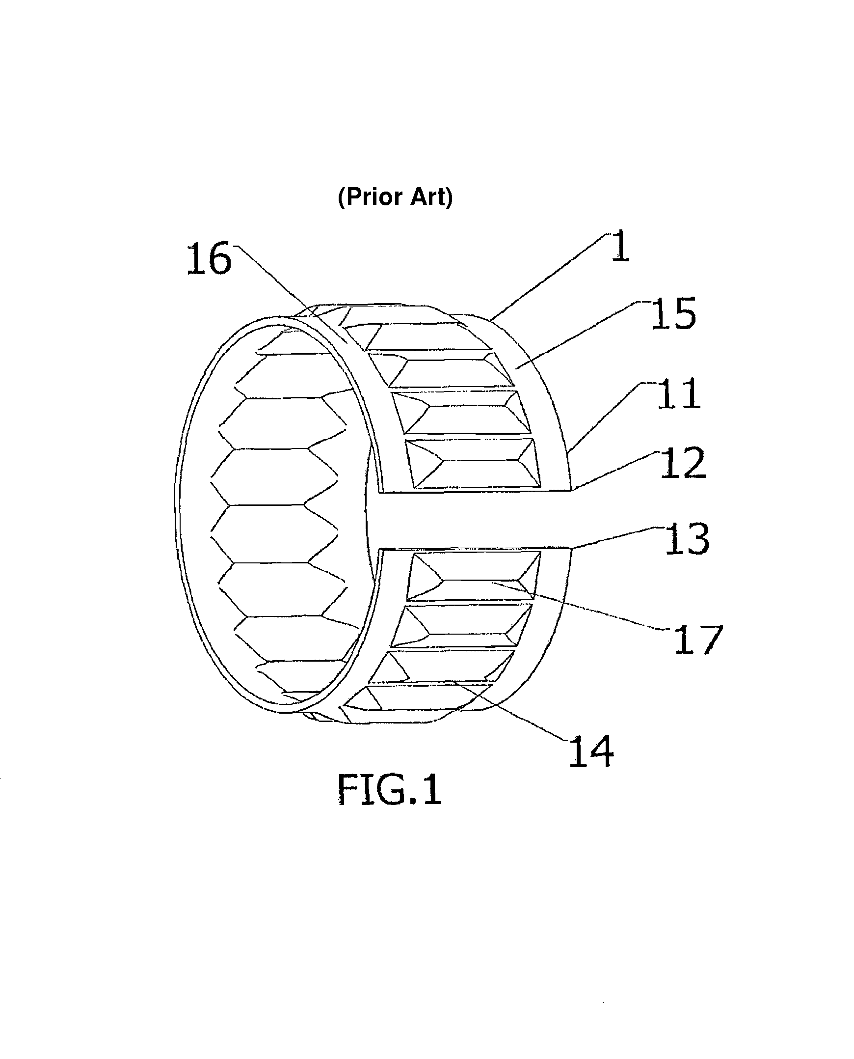
[0074]A known tolerance ring 1 is shown in FIG. 1. The tolerance ring 1 comprises a band of resilient material 11, for example a metal such as spring steel, the ends 12, 13 of which are brought together to form a ring. A strip of projections 14 extend radially outwards from the ring. The projections 14 are regular corrugated formations, and each has a peak 17. The strip of projections 14 is axially flanked by annular regions 15, 16 of the band of resilient material 11 that have no formations.

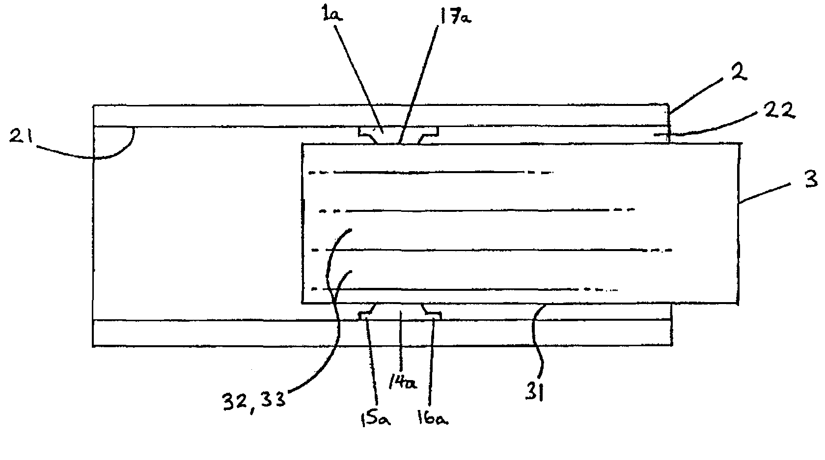
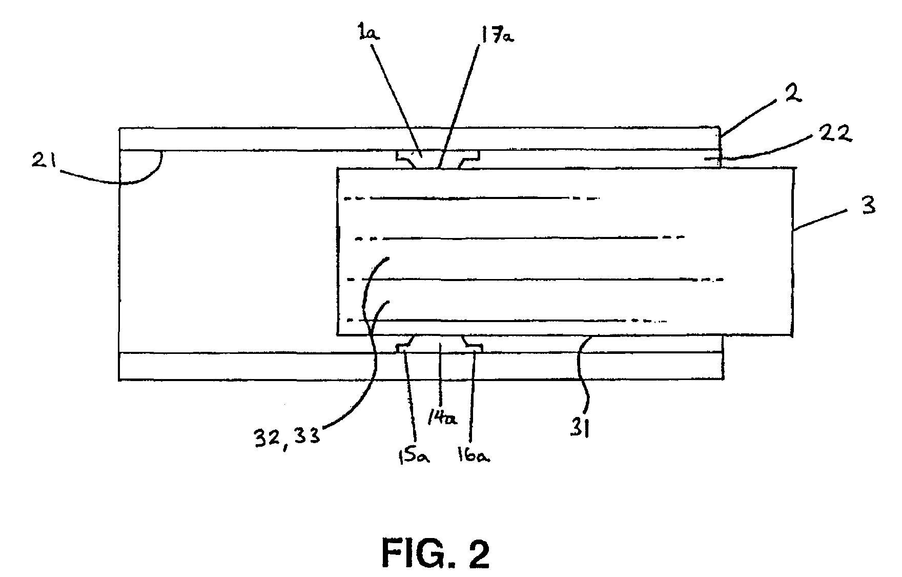
[0075]FIG. 2 shows a first embodiment of an apparatus according to the present invention. The apparatus includes two mating components 2, 3, which are components of a length-adjustable steering wheel column assembly. The first of the mating components is an inner tube (shaft) 3 of the steering column assembly. The second of the mating components is an outer jacket of the assembly, which essentially comprises a housing 2 having a bore 22 therein.

[0076]A tolerance ring 1a is located between the sh...


PUM

PropertyMeasurementUnit
radiusaaaaaaaaaa
surface radiusaaaaaaaaaa
distanceaaaaaaaaaa

Abstract

A shaft is held in place within a bore of a housing with a band of resilient material that is located between the shaft and the housing and has a series of projections extending radially inwards. The shaft surface has a first part that lies closer to the longitudinal axis of the bore than a second part, when the shaft and housing are assembled. The shaft is initially inserted into the resilient band, which is held within the bore, such that the first part of the shaft surface is oriented towards one of the projections of the resilient band. In this orientation of the shaft, the projection is not compressed. By orienting the second part of the shaft surface, the projection is brought under compression and the shaft is held firmly within the bore.

Description

CROSS-REFERENCE TO RELATED APPLICATION[0001]This application claims priority under 35 U.S.C. §119(a) to United Kingdom Application No. 0615672.3, filed on Aug. 7, 2006, the entire contents of which are incorporated herein in by reference.FIELD OF INVENTION[0002]1. Background of the Invention[0003]The present invention relates to a method of assembling an apparatus having a housing with a bore therein and a shaft received in the bore and connected thereto to be held in the bore. It also relates to an apparatus assembled by such a method, and also to a pre-assembly from which such an apparatus is assembled.[0004]2. Description of the Prior Art[0005]It is known to connect together a housing and a shaft received in a bore of the housing by a tolerance ring. The tolerance ring may be used to hold the shaft in place in the bore, or it may act as a force limiter to permit torque to be transmitted between the shaft and the housing. Tolerance rings are used, for example, to transmit torque p...

Claims


Application Information

Patent Timeline
Patent Type & Authority Patents(United States)
IPC IPC(8): B21D53/00F16C33/02
CPCF16D1/0817F16D7/022Y10T29/49544Y10T29/49844Y10T29/4987F16D2001/062F16C27/00F16C2370/12F16D1/0835
Inventor HUGHES, SIMON ALAN
Owner SAINT GOBAIN PERFORMANCE PLASTICS RENCOL
Why Eureka
Try Eureka