Damping and drilling machine including such a damping device

a damping device and drilling machine technology, applied in the direction of boring/drilling equipment, drilling machines and methods, percussive tools, etc., can solve the problems of ineffective drilling, short separation of drill string from drilling machine, and inability to handle tension reflexes directly by damping systems

Inactive Publication Date: 2011-06-14
ATLAS COPCO ROCK DRILLS
View PDF14 Cites 6 Cited by
  • Summary
  • Abstract
  • Description
  • Claims
  • Application Information

AI Technical Summary

Benefits of technology

[0013]It is an aim of this invention to provide a damping device, wherein the problems with the background art are solved or at least reduced. In particular it is an aim to provide a damping device which is fast as well as energy saving.
[0015]Hereby it is achieved that the first damping piston can be dimensioned such that a feeding force on the machine housing, in advance positions of this damping piston, is capable of pressing this first damping piston backwardly in the direction of the second damping piston. The function of the first damping piston will thereby be to, when it is necessary, follow the drill string forwardly in order to obtain rock contact for the drill bit. This results in contact with the machine and better tightening of joints etc.
[0016]The second damping piston operates in principle as a conventional single damper. It has the function to protect the machine against harmful shockwaves reflected from the rock, which have such force that they press the first damping piston to retracted positions, wherein both damping pistons, exerts a force on the drill string. It has further a function to achieve a defined striking position, which contributes to better percussion machine power.
[0017]Hereby is obtained a great number of advantages, namely that the machine is effectively protected, against reflected shock waves. The system can be made fast so that the machine can quickly follow the drill string and in particular the adapter forwards for achieving a good tightening of joints. An almost unequivocal striking position is defined for the machine whereas the energy consumption for the damping device is reduced.
[0019]In case of concentrically positioned damping pistons according to the invention, the advantage of saving room is obtained in an axial direction, which results in that the entire drilling machine construction can be made relatively short. By the construction according to the invention it is possible also that none of the damping devices according to the invention consumes any power, since no continuous oil flow according to the above is necessary.

Problems solved by technology

Tensile reflexes can not be handled directly by damping systems of the older type.
A sudden cavity in the rock can thus result in that the drill string for a short while separates from the drilling machine.
This results in ineffective drilling.
A problem with this kind of arrangement is the increased energy consumption which is caused by the need of a constant flow of hydraulic liquid.
In particular in case of low feeding force, contact between the damping piston and the shank adapter is lost already before the strike occurs.
Also during this movement, there is a lack of transfer of feeding force to the drill string and thereby rotational resistance.
More energy saving damping devices have, however, resulted in slow systems with relatively long periods without contact between a damping piston and the adapter, resulting in that during considerable periods, no feeding force has been transferred to the drilling steel, whereby no tightening of joints occurs in the drill string and ineffective drilling will be the result.

Method used


Image

  • Damping and drilling machine including such a damping device
  • Damping and drilling machine including such a damping device
  • Damping and drilling machine including such a damping device

Examples


Embodiment Construction

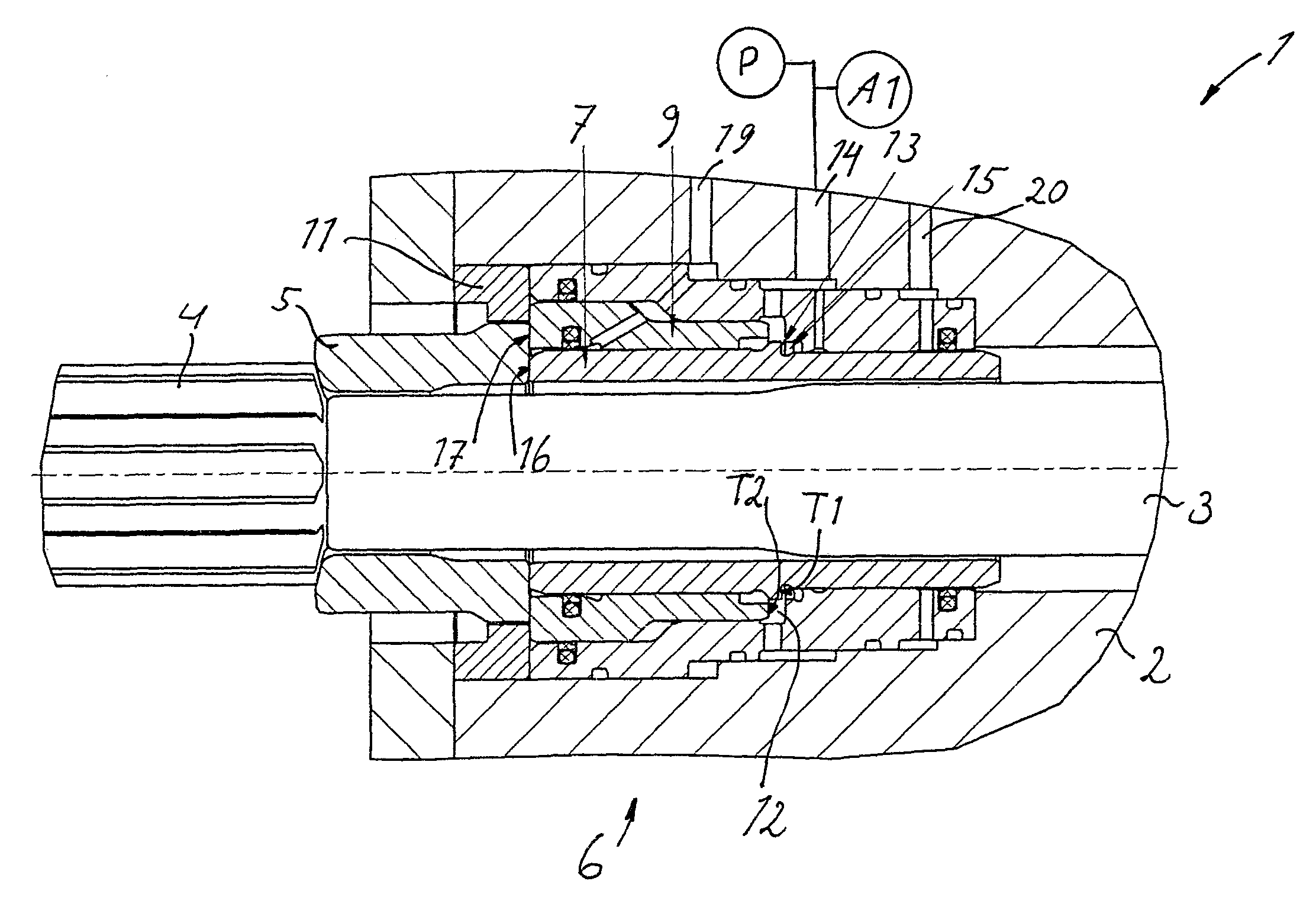
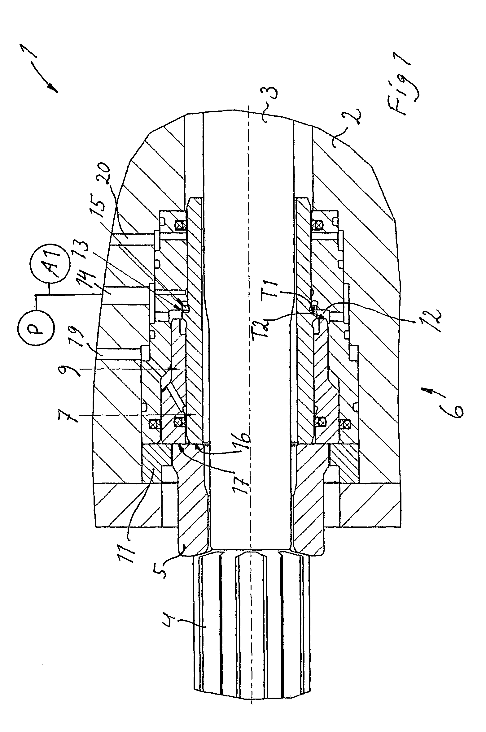
[0025]In FIG. 1 is shown a detail 1 of a percussion drilling machine including a part 2 of a housing, wherein a percussive piston 3 is moveable to-and-fro in a per se previously known manner. The percussion piston 3 acts by striking against the upper end of a shank adapter 4, whereto are connected not shown drill string elements and, most distal, a not shown drill bit.

[0026]On a surface radially outside the stroke-receiving end surface, the shank adapter 4 provides a contact surface for a drill bushing 5, which in turn, on its other end, is actuated by a damping device 6.

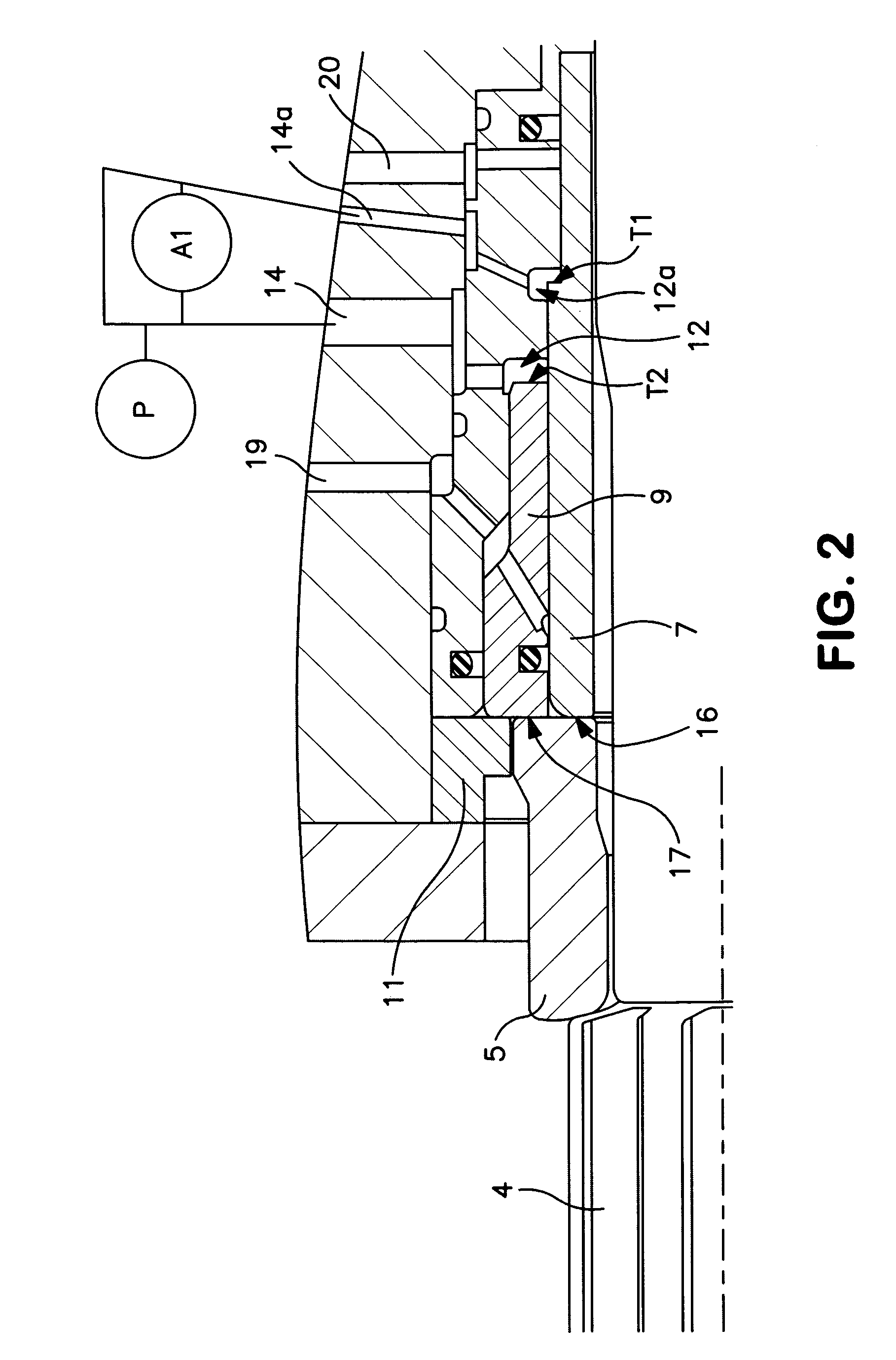
[0027]The damping device 6 includes according to the invention a first damping piston 7, which contacts directly against said drill bushing 5, and which has a pressure surface T1 positioned inside a damping volume (or damping chamber) 12. The damping volume 12 is over a hydraulic oil channel 14 in connection with a pressure source P and a hydraulic / pneumatic accumulator A1, through which is maintained a damping pres...


PUM

PropertyMeasurementUnit
pressureaaaaaaaaaa
forceaaaaaaaaaa
energy absorptionaaaaaaaaaa

Abstract

A damping device for inserting into a housing of an impulse producing drill machine, for damping Shockwave reflexes from a drill string connected to the drilling machine, is distinguished in that a first damping piston (7) for direct or indirect action against the drill string and for applying a pressure in the direction of the drill string an a second damping piston (9) for applying pressure in the direction against the drill string against a fixed stop (11) arranged in the housing, wherein the first (7) and the second damping piston (9) are arranged to co-operate for joint damping action with a drill bushing or shank adapter in a certain relative position. The invention also concerns a drilling machine.

Description

FIELD OF THE INVENTION[0001]The invention concerns a damping device according to the preamble of claim 1 and a drilling machine including such a damping device.BACKGROUND OF THE INVENTION[0002]In drilling machines for rock drilling having a drill string and a drill bit at its distal end, the drill string adjoins to a drilling machine over an adapter, having its axial contact with the drilling machine against a drill bushing. In a previously known percussion drilling machine with rotation means, the contact between the adapter and the drill bushing is typically achieved through contact of the latter against axial ends of the rotational splines of the adapter.[0003]Against the end of the drill bushing which is turned away from the drill string, acts the so called damping piston, which functions so as to transfer the feed force against the rock from the machine housing to the drill bushing and further over the adapter, over the drill string to the drill bit for contact thereof against ...

Claims


Application Information

Patent Timeline
Patent Type & Authority Patents(United States)
IPC IPC(8): B25D9/00B23B45/16
CPCB25D17/24E21B17/07E21B4/14B25D17/245E21B1/00E21B1/38
Inventor LARSSON, PER-ERIKOSTLING, THOMAS
Owner ATLAS COPCO ROCK DRILLS
Why Eureka
Try Eureka