Dual air vent bypass (DAVB) container

a technology of bypassing and air venting, applied in the field of containers, can solve problems such as growing void spaces

Active Publication Date: 2011-06-14
ALHARR TECH
View PDF24 Cites 36 Cited by
  • Summary
  • Abstract
  • Description
  • Claims
  • Application Information

AI Technical Summary

Benefits of technology

[0007]In a more particular embodiment, the center handle channel and the base channel are joined at a bifurcation and travel to the manifold region along a slightly tilted path. The tilted path permits fluid trapped in either of the channels to drain to the rear of the container into the vacuum manifold region where the center handle channel and the base channel terminate. Permitting the channels to drain insures that the channels are clear and able to deliver air from the air vent opening via the dual air vent

Problems solved by technology

However, as the container is tilted to cause fluid to leave the pouring spout,

Method used


Image

  • Dual air vent bypass (DAVB) container
  • Dual air vent bypass (DAVB) container
  • Dual air vent bypass (DAVB) container

Examples


Embodiment Construction

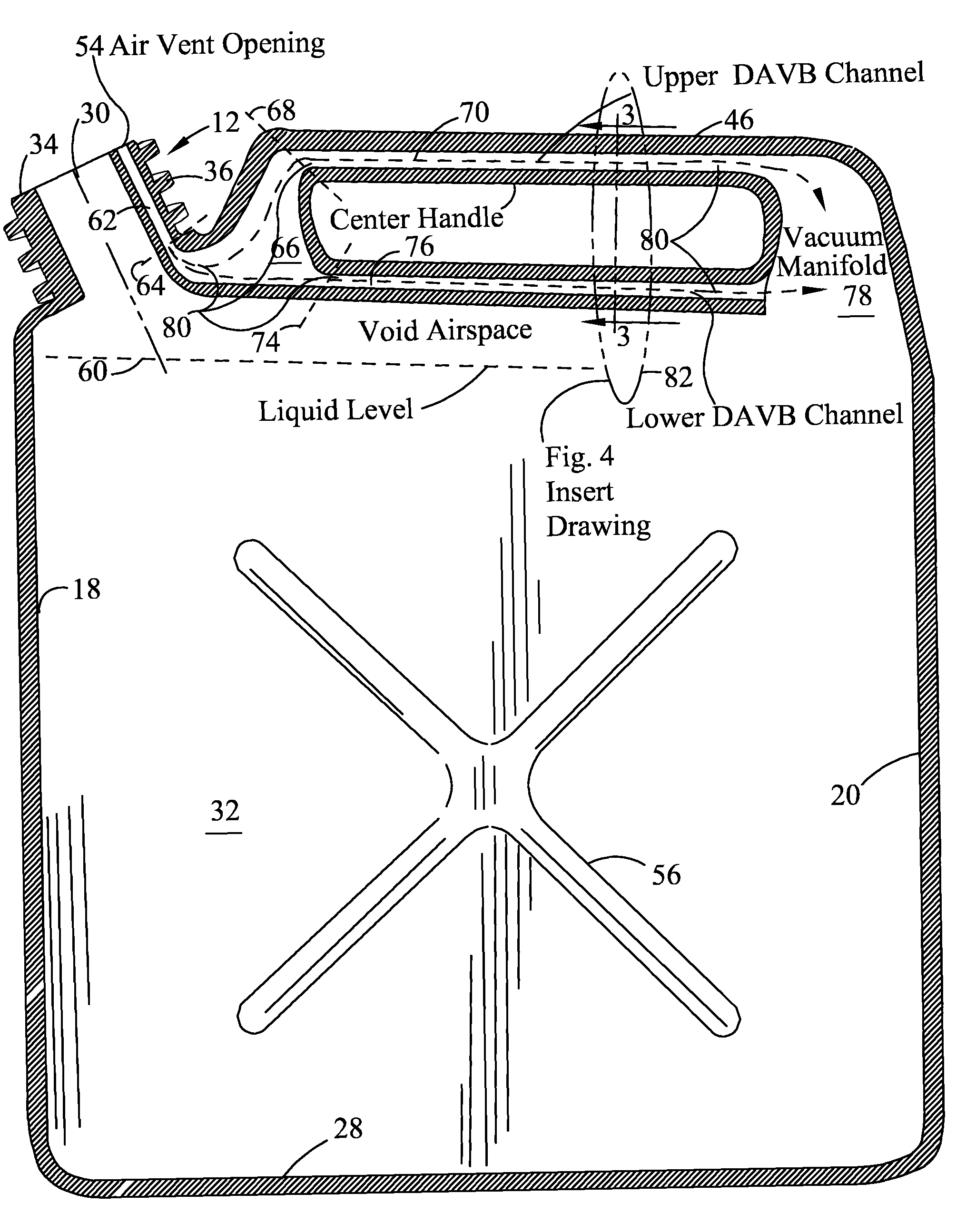
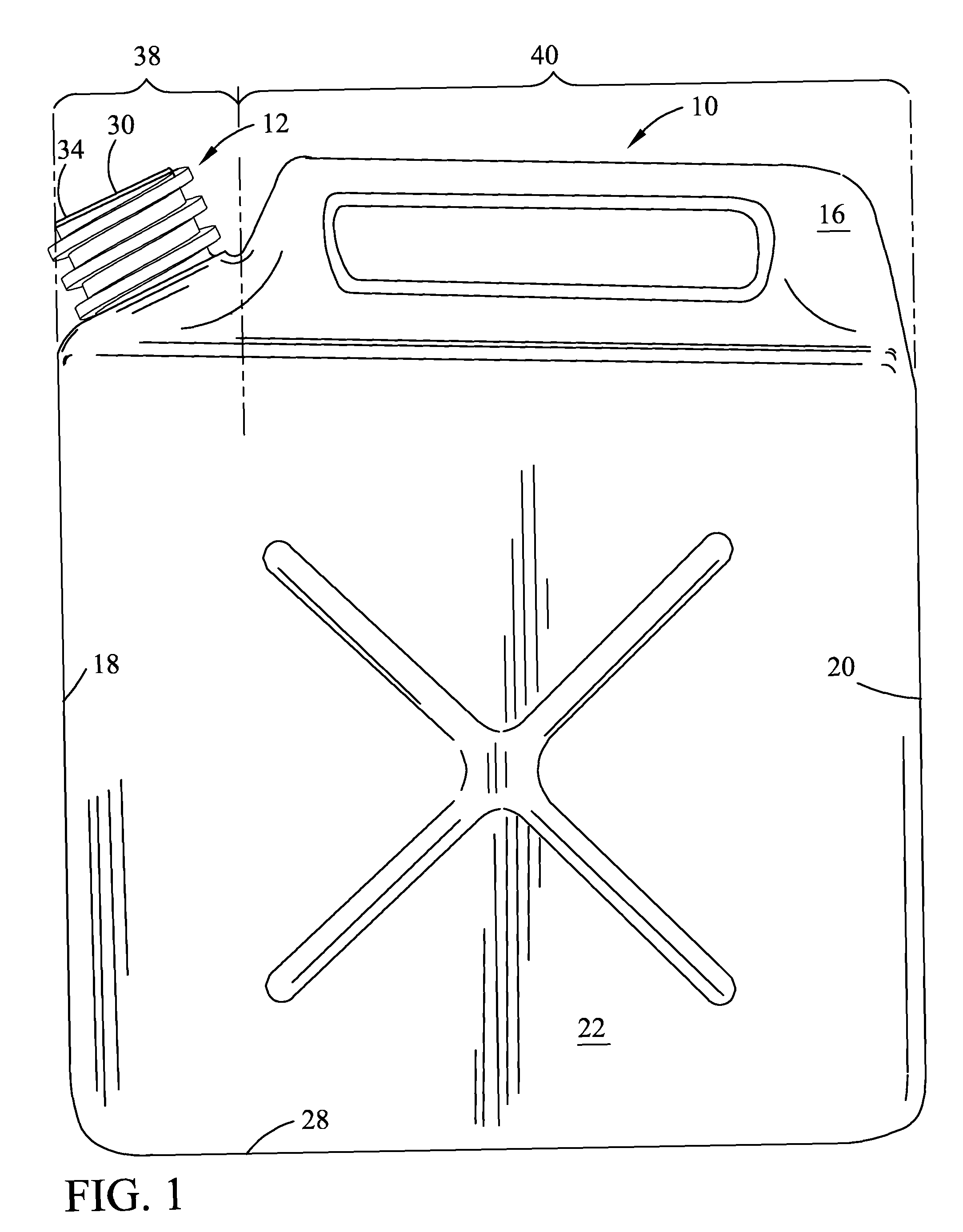
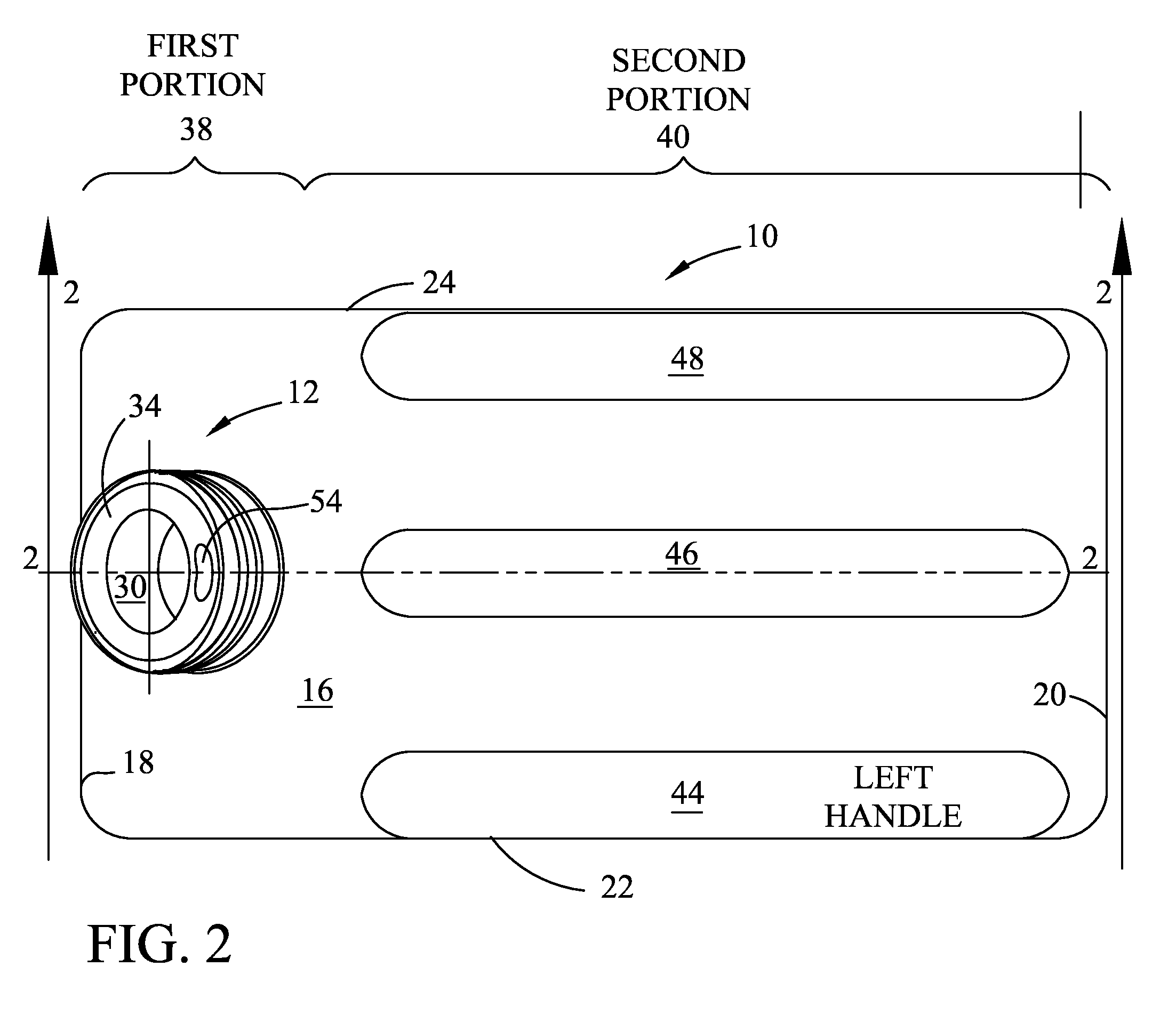
[0016]Referring now to the drawings, FIG. 1 shows a container 10 for dispensing liquids such as water or fuel. As shown in FIGS. 1 and 2, container 10 has a circular threaded pouring spout 12 integrally formed on a cover 16. The cover 16 is integrally formed onto the top ends or edges of four vertical walls that extend upward from a base wall 28, the vertical walls include vertical front wall 18, rear wall 20, left side wall 22 and right side wall 24. The base wall 28 is integrally joined to the bottom ends or edges of the respective vertical front wall 18, rear wall 20, left side wall 22 and right side wall 24 thereby forming a container that is suitable for holding fluids. The cover is integrally coupled to the top or upper wall ends or edges by welding, bonding or molding as in blow molding. The base wall 28 is also integrally coupled to the bottom or lower ends or edges of the walls by welding, bonding or molding as in blow molding construction, as required to form the container...


PUM


Abstract

A container for dispensing a fluid with no contraction/expansion “glug, glug” effect has a cover forming a sealed top with a pouring spout on top of the cover and at least one elongated handle on top of the cover. The elongated handle extends longitudinally away from the pouring spout and has a distant end coupled to a vacuum manifold formed under the cover as a void space distant from the pouring spout and above fluid within the fluid tight container. A pouring spout has a circular aperture leading into the fluid tight container. The circular aperture has a central axis; the circular aperture is bordered by a peripheral circular sealing surface that extends radially away from the aperture. An air vent opening is positioned on the circular aperture's highest radial central position on the circular sealing surface. A dual air vent bypass channel delivers air entering the air vent opening via a top channel through the elongated handle to the vacuum manifold, and via a bottom channel under the cover to the vacuum manifold.

Description

[0001]This application claims the benefit of the priority date of Provisional Patent Application Ser. No. 61 / 395,553 filed May 17, 2010.FIELD OF THE INVENTION[0002]This invention relates to containers for dispensing liquids such as water or fuel and more specifically to a container having a pouring spout with a circular aperture bordered by a circular sealing surface sealed by a cap and a gasket. The pouring spout circular aperture leads to a liquid containing chamber. More particularly, this invention relates to those containers that provide an air vent opening from the pouring spout that leads to the space above the liquid to permit air to be drawn into the space above the liquid during a pouring operation to prevent the contraction / expansion (glug, glug) phenomenon associated with conventional containers.BACKGROUND OF THE INVENTION[0003]This invention is particularly applicable to blow-molded plastic containers used for dispensing a variety of different types of liquids, some of ...

Claims


Application Information

Patent Timeline
IPC IPC(8): B65D83/00
CPCB65D1/20B65D25/2894B65D47/06B65D51/1611B65D25/48B65D2205/02Y10S215/902B65D2205/00
Inventor CHRISTIAN, ALLEN B.HARR, ROBERT K.
Owner ALHARR TECH
Why Eureka
Try Eureka