USB connector and its fabrication method
a technology of usb connectors and fabrication methods, applied in the direction of coupling contact members, contact member manufacturing, coupling device connections, etc., can solve the problems of increasing die cost and die preparation time, waste of metal sheets, and data transmission speed cannot meet the demand for quick, so as to save the manufacturing process and save the cost of many dies , the effect of saving much fabrication time and installation cos
- Summary
- Abstract
- Description
- Claims
- Application Information
AI Technical Summary
Benefits of technology
Problems solved by technology
Method used
Image
Examples
first embodiment
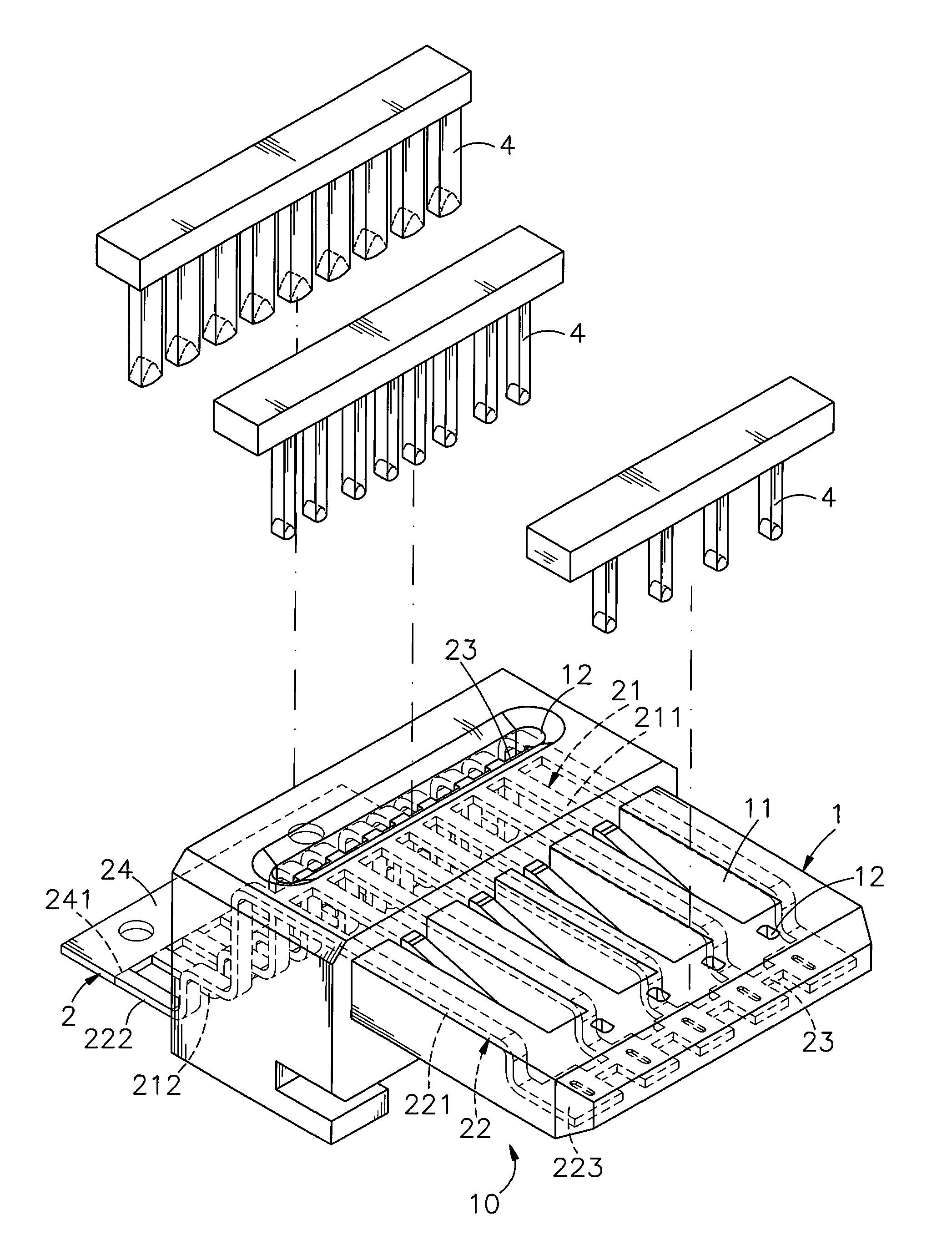
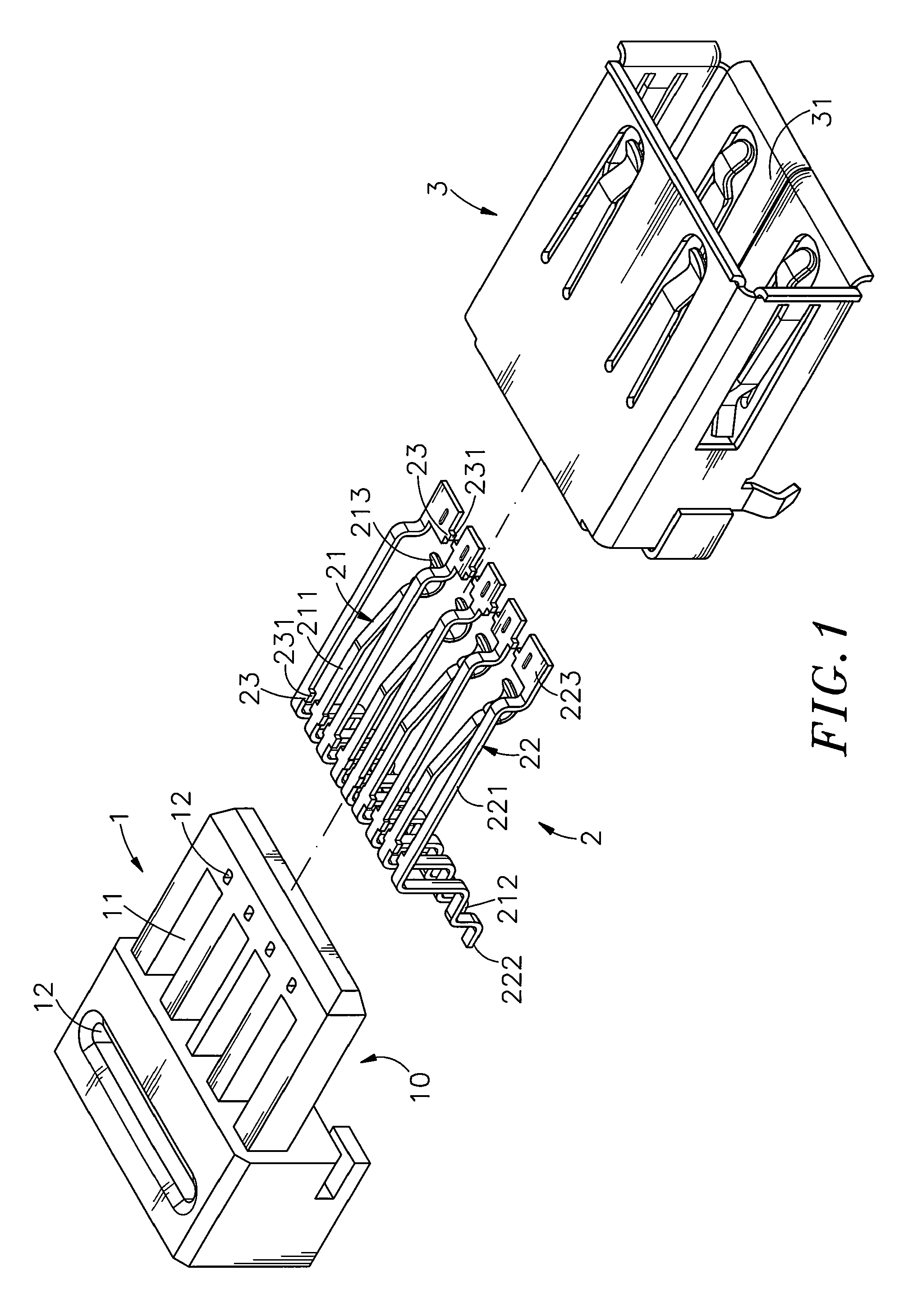
Referring to FIG. 1 and FIG. 6, a USB (universal serial bus) connector in accordance with the present invention is shown comprising an electrically insulative housing 1, a terminal set 2 and a metal shield 3.
The electrically insulative housing 1 defines a receiving space 10, a plurality of suspension slots 11 arranged in a parallel manner in communication with the receiving space 10 and a plurality of punch holes 12 arranged at front and rear sides relative to the suspension slots 11.
The terminal set 2 is mounted in the electrically insulative housing 1, comprising a set of first terminals 21, a set of second terminals 22 and a plurality of material bridges 23 joining the first terminals 21 and the second terminals 22. The first terminals 21 and the second terminals 22 are alternatively arranged in a row and connected to one another by the material bridges 23, each having a narrow elongated base portion 211 or 221, a rear bonding end portion 212 or 222 backwardly extended from one e...
second embodiment
FIGS. 7 and 8 show a USB (universal serial bus) connector in accordance with the present invention. According to this second embodiment, the first terminals 21 and the second terminals 22 each have a narrow elongated base portion 211 or 221, a rear bonding end portion 212 or 222 backwardly extended from the rear end of the narrow elongated base portion 211 or 221, and a front contact end portion 213 or 223 forwardly extended from the front end of the narrow elongated base portion 211 or 221, wherein the narrow elongated base portion 211 of each first terminal 21 has a front connection segment 2111 sloping upwardly forwards; the front contact end portion 213 of each first terminal 21 is shaped like a flat strip and extends forwardly from the front connection segment 2111 of the associating narrow elongated base portion 211 in horizontal and then sloping downwards; the narrow elongated base portion 221 of each second terminal 22 has a front connection segment 2211 sloping upwardly for...
PUM
| Property | Measurement | Unit |
|---|---|---|
| shape | aaaaa | aaaaa |
| electrically | aaaaa | aaaaa |
| transmission speeds | aaaaa | aaaaa |
Abstract
Description
Claims
Application Information
 - R&D
- Intellectual Property
- Life Sciences
- Materials
- Tech Scout
- Unparalleled Data Quality
- Higher Quality Content
- 60% Fewer Hallucinations
Browse by: Latest US Patents, China's latest patents, Technical Efficacy Thesaurus, Application Domain, Technology Topic, Popular Technical Reports.
© 2025 PatSnap. All rights reserved.Legal|Privacy policy|Modern Slavery Act Transparency Statement|Sitemap|About US| Contact US: help@patsnap.com


