Heating system to alleviate hypothermia

a heat exchanger and hypothermia technology, applied in the field of heat exchangers for maintaining or restoring normothermia, to achieve the effects of reducing the risk of hypothermia, facilitating patient insertion, and preventing significant stray heat in the limbs

Active Publication Date: 2011-06-14
GRI ALLESET INC
View PDF15 Cites 3 Cited by
  • Summary
  • Abstract
  • Description
  • Claims
  • Application Information

AI Technical Summary

Benefits of technology

[0005]Applicants' physiological and thermodynamic research indicates that effective rewarming of a significantly hypothermic human: a) greatly exceeds the capacity of passive warming; b) preferably avoids or reduces major limb rewarming; and c) the active application of heat is preferably selectively applied to accommodate large locale-dependent variations in body surface heat uptake capabilities. The areas most conducive to efficient heat uptake are the head, neck, chest (including the shoulders and armpits; hereafter, “chest” shall denote the extended area) and abdomen. It has also been determined for one embodiment that the heat-generating covering may be preferably tight fitting or otherwise in good contact for more efficient transfer of heat to the body surface and ultimately the body core (in general, deep structures of the torso, neck and head). Restoring body core temperature to normal is typically the goal of therapy.
[0007]In one embodiment, a heating system is disclosed that may be considered to be relatively aggressive in treatment of hypothermia. This may be similar to a close-fitting jump suit, which substantially envelopes of the entire body, except for, in certain embodiments, the face and the distal two-thirds of the limbs. Such a design can be viewed as a modified jump suit in two basic parts, configured much like a hooded sleeping bag that can be completely unzipped to separate a bottom half that lies on a supporting surface, and a top half that may be separate and removable. For example, one could envision the bottom half of the thermal cover laid flat, the subject placed longitudinally on said bottom half, and then the top half placed over the subject and fastened around the entire mutual circumferences of the top and bottom halves. A close fit may be aided by the modest tension which arises from special cover design features as described later.
[0008]For the aggressive treatment example, several structural and functional modifications of today's typical jump suit are desired to present structure and function. First, the arm and leg elements may be shortened so that only short lengths extend from the torso. This facilitates patient insertion and better guards against significant stray heating of the limbs. Second, as described, the jump suit may be entered and closed around the sides of a supine subject, not, for example, circumferentially at the waist, to aid patient insertion and to optimize any need to occasionally access trauma sites anywhere along the long axis of the subject. Third, the head and neck may be covered by connecting flaps that extend from either the top or bottom jump suit halves. Fourth, the jump suit exit openings for each arm and leg are loosely conforming, not tightly sealed, to permit minor heat leakage from within the actively heated jump suit (more details later). Fifth, with regard to the head hood, a purse-string or other means may be employed to create a reasonably good seal to prevent heat leakage around the face perimeter. Note that some leakage may be acceptable at the arm and leg exits (explained later), but may be undesirable at the opening for the face. Finally, the modified jump suit features active heating, to address the extraordinary quantity of heat desired to restore normothermia in a severely or moderately hypothermic subject. The heating element may be preferably a distributed pattern of thermal wire or a heat conducting fabric or gel that may be electrically heated by portable power means, e.g., batteries. However, other forms of active heating power (e.g., fuel-based or phase-change processes) and distribution (e.g., circulating fluid, ceramic elements, or carbon-based materials) are potentially available as well.

Problems solved by technology

Note that some leakage may be acceptable at the arm and leg exits (explained later), but may be undesirable at the opening for the face.

Method used


Image

  • Heating system to alleviate hypothermia
  • Heating system to alleviate hypothermia
  • Heating system to alleviate hypothermia

Examples


Embodiment Construction

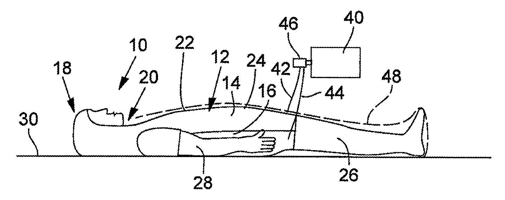
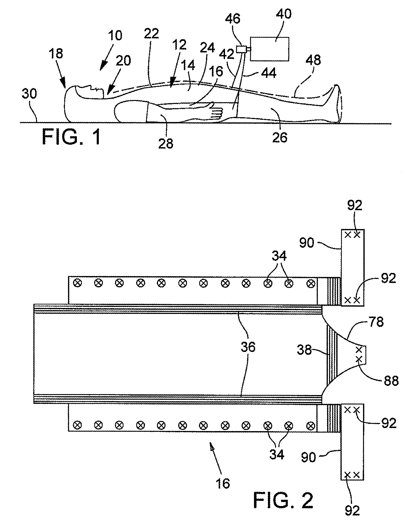
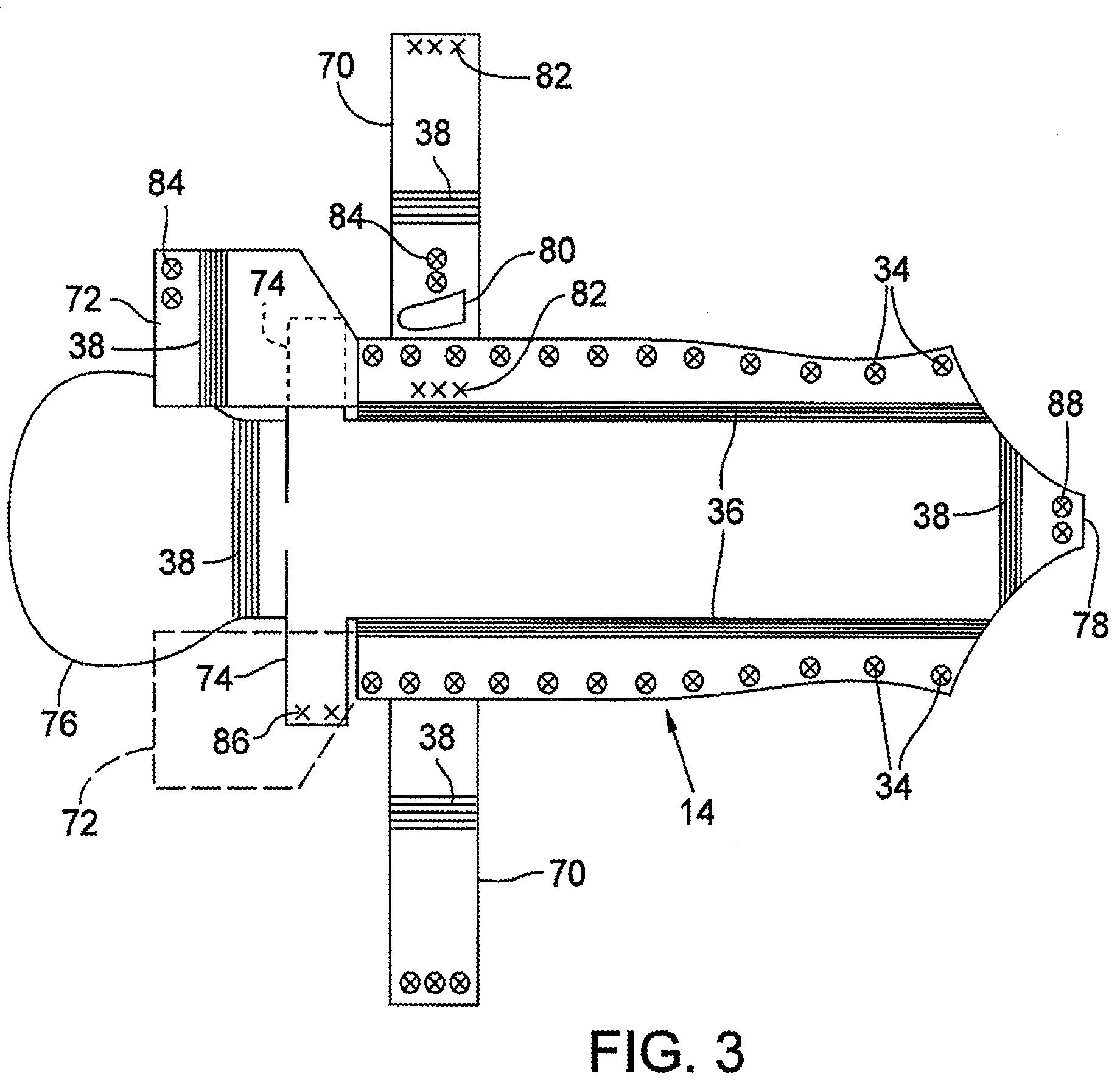
[0017]FIG. 1 illustrates an injured person 10 enclosed in a medical thermal cover of an exemplar aggressive embodiment 12. The thermal cover 12 may be comprised of a top portion 14 (shown in top view in FIG. 3) and a bottom portion 16 (shown in top view in FIG. 2).

[0018]It is determined that major portions (Zones) of four areas of a person's body have optimum peripheral and deep blood flow for dispensing heat: (a) most or all of the head 18 (excluding the face); (b) most or all of the neck 20; (c) most or all of the chest 22 (including the shoulders and armpits as well); and (d) most or all of the abdomen 24. The latter four Zones may be in the upper body portion (subject supine as shown in FIG. 1) or the front side body portion (subject upright). Thus, the thermal cover may be split to provide top portion 14 and bottom portion 16 whereby the top portion 14 of the thermal cover contains sizeable sub-areas (Zones) that constitute the four Primary Zones for active heating, while the b...


PUM


Abstract

A medical, electrically powered thermal cover for fitting predominantly the trunk and head of a person experiencing or potentially experiencing traumatic or cold-exposure hypothermia. The thermal cover encases all of the torso and neck, and portions of other body areas. Heating may be distinctly non-uniform, being applied to the body surface only in special regions where the body's capacity for heat uptake may be relatively high. In sum, the system may monitor deep body core temperature, direct heat to the body core where it may be most needed, and controls therapy over time to restore normothermia.

Description

RELATED APPLICATION[0001]This application is a non-provisional application claiming priority from provisional application No. 60 / 682,531 filed on May 18, 2005.FIELD OF INVENTION[0002]This invention relates to heating systems for maintaining or restoring normothermia in persons who are potentially or actually hypothermic, particularly during preparation, staging and transport from a remote location to a relevant medical facility.BACKGROUND OF THE INVENTION[0003]It is known that significant trauma or cold exposure to a person often induces hypothermia (health threatening reduction of core body temperature), which can compound medical consequences. Thus, it is desirable to provide additional heat in addition to normal body-generated heat, e.g., apply warming covers to the injured person.[0004]It is preferred that the covers are provided with electric or other active heating to enhance the warming properties of the covers. However, known warming covers as applied to an injured person ha...

Claims


Application Information

Patent Timeline
Patent Type & Authority Patents(United States)
IPC IPC(8): A61F7/00
CPCA61F7/007A61F2007/0234A61F2007/0071A61F2007/0001
Inventor FIELDS, R. WAYNECAMPF, MELVIN F.CRAWSHAW, LARRY I.HOMAYOUN, HABIBMILLS, GARYROBINSON, JOHN D.RECKTENWALD, GERALDCHAMBERS, PETE
Owner GRI ALLESET INC
Why Eureka
Try Eureka