Portable wave-swash and coastal-wind energy harvester

Inactive Publication Date: 2011-06-21
JOSEPH ERAT S
View PDF16 Cites 13 Cited by
  • Summary
  • Abstract
  • Description
  • Claims
  • Application Information

AI Technical Summary

Benefits of technology

[0014]The apparatus harnesses the energy of waves as well as that of wind simultaneously through the combined utilization of the wave turbines, the wind turbines, and the wave floats, complemented by the wave funnel, the flywheels, the buoyancy chamber, the stabilization tank, and other embodiments. Portability of the unit on land, its maneuverability in water, and its stability in the operational location are some of the key features. The wind turbines and the wave funnel can be assembled or disassembled at site, a feature which makes it feasible to transport the apparatus to the site in a truck.
[0015]Harnessing of energy from waves and wind simultaneously and the utilization of a combination of the wave turbines, the wind turbines, and the wave floats, complemented by the flywheels result in substantially steady rotation of the axles and a consequent

Problems solved by technology

The description states, “The turntable is rotated on bearings over a fixed-horizontal base plate, until the set-up is facing the wind and waves directly to the best advantage.” One of the deficiencies of the apparatus is due to the fact that the directions of wind and wave do not necessarily match, and while the horizontal-axis wind wheel will not work unless its orientation changes to face the wind, a water wheel will not work unless it faces water flow.
It is not designed for operation in the wave swash zone.
None of the above mentioned patents includes any device to assist in the retention of angular momentum for maintaining sustained rotational energy.
Despite the fact that abundant energy is available in wind and in sea waves, capturing of this energy economically from these sources remains a technological challenge.
One of the major drawbacks of wind mill technology lies in its very low capacity factor—the ratio of the power actually produced to the power that would have been produced if the turbines operated 100% of the time.
Standard wind mills are huge in size, and are economically not feasible.
One of the difficulties faced by wave turbine technology is due to the periodic nature of the occurrence of the waves and the resulting variability of torque produced by wave turbines.

Method used


Image

  • Portable wave-swash and coastal-wind energy harvester
  • Portable wave-swash and coastal-wind energy harvester
  • Portable wave-swash and coastal-wind energy harvester

Examples


Embodiment Construction

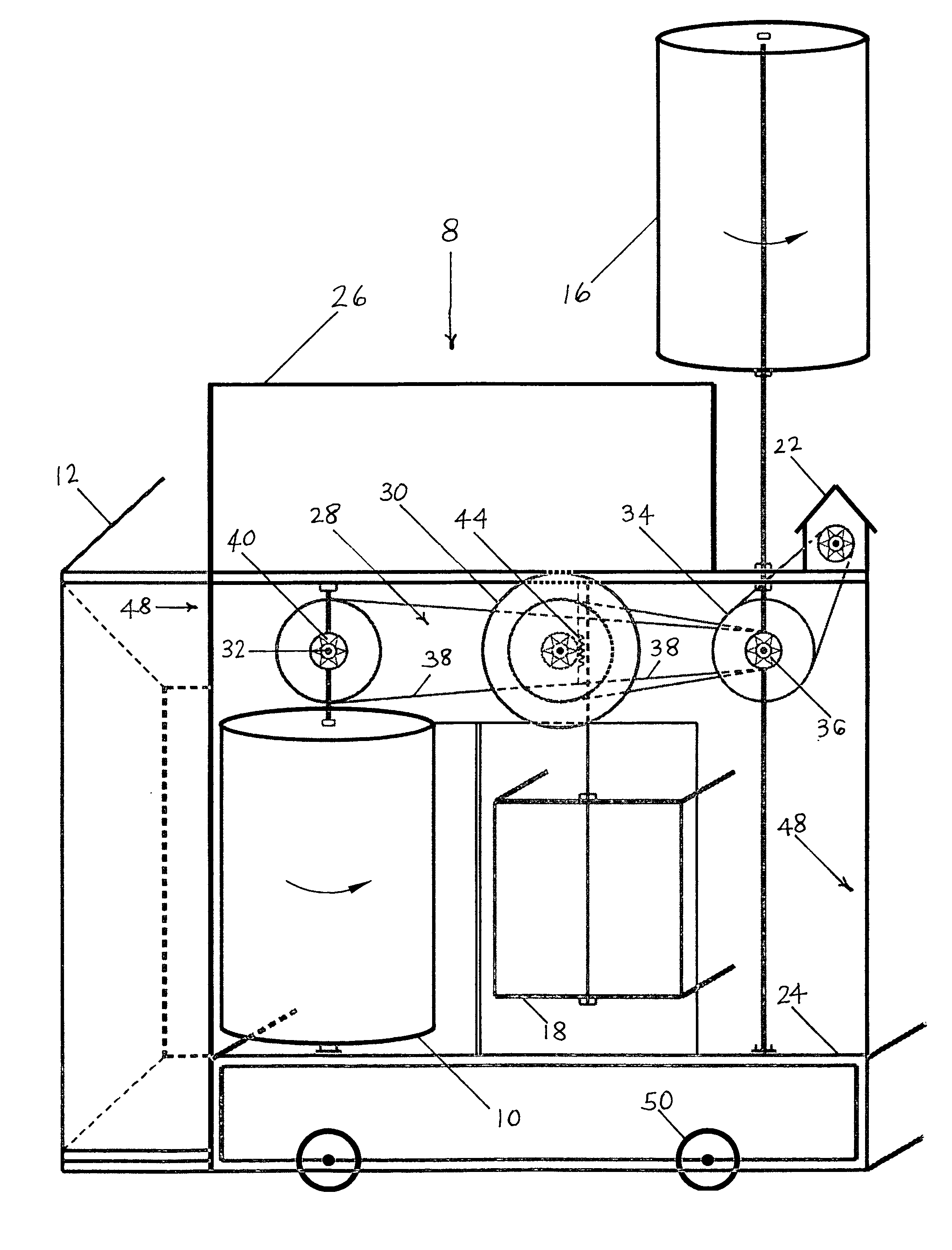
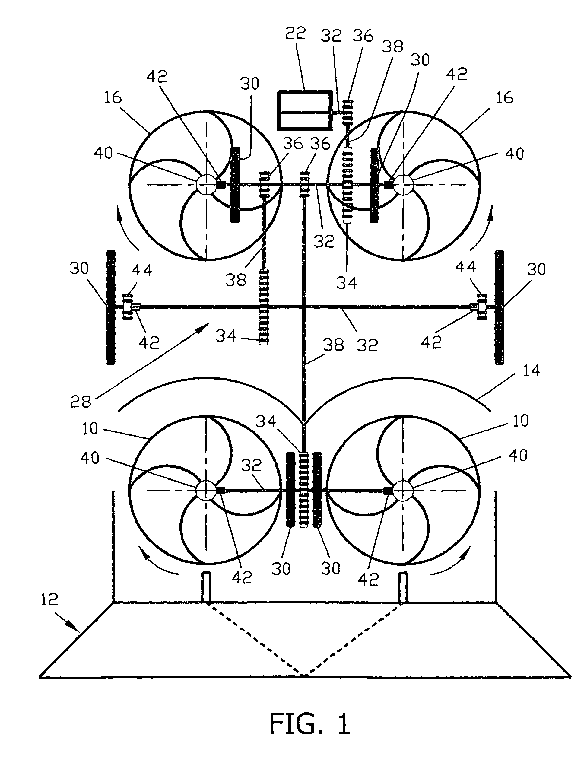
[0062]FIG. 1 is the top view of the portable wave-swash & coastal-wind energy harvester invention 8. Included elements: wave turbines 10, wave funnel 12, wave-turbine cover 14, wind turbines 16, alternator 22, rotational transmission system 28, flywheels 30, axles 32, large sprockets 34, small sprockets 36, roller chains 38, bevel gears 40, one-way clutches 42, and rack and pinion gears 44. Excluded for clarity from FIG. 1 are the following elements: wave floats 18, float restraint 20, buoyancy chamber 24, stabilization tank 26, bearings 46, frame 48, and wheels 50.

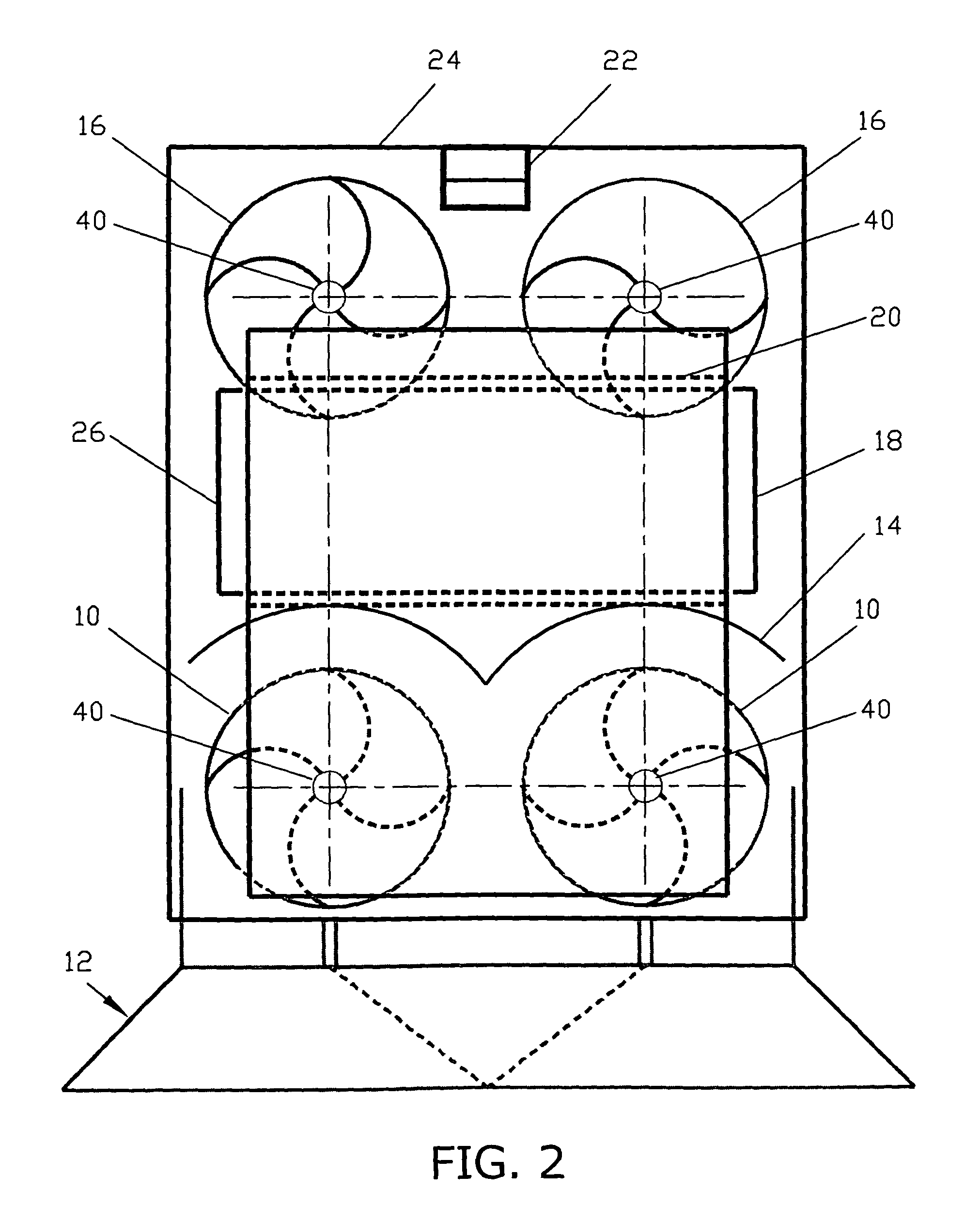
[0063]FIG. 2 is an additional top view of the portable wave-swash & coastal-wind energy harvester invention 8. Included elements: wave turbines 10, wave funnel 12, wave-turbine cover 14, wind turbines 16, wave floats 18, float restraint 20, alternator 22, buoyancy chamber 24, stabilization tank 26, and bevel gears 40. Excluded for clarity from FIG. 1 are the following elements: rotational transmission system 28, flywheels...


PUM


Abstract

In accordance with the present invention, a portable wave-swash & coastal-wind energy harvester, once placed on a sea coast in the swash zone captures the mechanical energy contained in: (a) waves in the swash-zone, and (b) coastal-wind. Energy is extracted through: (a) wave turbines, (b) wind turbines, and (c) wave floats. A rotational transmission system with one-way clutches transmits torque to an alternator, while flywheels attached to the axles maintain steady rotation of axles. A wave funnel faces the waves and causes the wave uprush to converge toward wave turbines. A buoyancy chamber at the bottom produces reduction of weight of the portable wave-swash & coastal-wind energy harvester when water in the chamber is emptied and thereby enhances maneuverability of the unit on land and in water, while a stabilization tank at the top when filled with water provides extra weight and stability of the unit in its operating location.

Description

RELATED APPLICATIONS[0001]The present application is a continuation-in-part application of U.S. provisional patent application Ser. No. 61 / 214,379, filed Apr. 23, 2009, for PORTABLE WAVE-SWASH & COASTAL-WIND ENERGY HARVESTER, by Erat S. Joseph, included by reference herein and for which benefit of the priority date is hereby claimed.FIELD OF THE INVENTION[0002]The present invention relates to the simultaneous capturing of the energy contained in sea waves and in wind.BACKGROUND OF THE INVENTIONBackground[0003]The following is a tabulation of some prior art that presently appears relevant U.S. patents[0004]U.S. Pat. No.Date of PatentPatentee3,687,567Aug. 29, 1972William C. Lininger4,319,454Mar. 16, 1982Louis V. Lucia4,392,060Jul. 5, 1983Jessie T. Ivy4,719,754Jan. 19, 1988Kochi Nishikawa5,005,357Apr. 9, 1991Mansel F. Fox5,244,359Sep. 14, 1993David M. Slonim5,549,445Aug. 27, 1996Edward J. Schremp6,109,863Aug. 29, 2000Larry D. Milliken6,269,636 B1Aug. 7, 2001Constantinos Hatzilakos6,559...

Claims


Application Information

Patent Timeline
IPC IPC(8): F03B17/02H02P9/04F03B13/10F03B13/18
CPCF03B13/144F03B13/183F03D9/008Y02E10/72F05B2260/421Y02E10/38F03D3/02F03D9/12F03D9/25F03D13/25F03D15/10Y02E10/30Y02E10/727Y02E60/16Y02E70/30
Inventor JOSEPH, ERAT S.
Owner JOSEPH ERAT S
Why Eureka
Try Eureka