LED lamp

a technology of led lamps and diodes, which is applied in the direction of discharge tube main electrodes, semiconductor devices of light sources, lighting and heating apparatus, etc., can solve the problems of short lamp life, heavy filler materials, and high power, and achieve stable positioning, reduce the operational time of installation, and prevent the effect of error installation

Inactive Publication Date: 2011-06-21
SKYNET ELECTRONICS
View PDF3 Cites 73 Cited by
  • Summary
  • Abstract
  • Description
  • Claims
  • Application Information

AI Technical Summary

Benefits of technology

[0010]An object of the present invention is to provide an LED (light emitting diode) lamp, which comprises a heat dissipation housing, an insulation housing, an electrode cap, a power printed circuit board (PCB), at least one LED, an installation base plate and a lamp shade, wherein the heat dissipation housing is formed with a receiving hole axially passed therethrough, and a position of an upper end of the heat dissipation housing adjacent to the receiving hole is formed with an engaged indentation. The insulation housing is made of insulation material, and the profile of the insulation housing can be installed into the receiving hole. An upper end of an outer periphery of the insulation housing is radially extended to form a projection which can be inserted and engaged into the engaged indentation in a case that the insulation housing is installed in the receiving hole. Furthermore, each of two opposite positions of an inner periphery of the insulation housing is axially formed with a positioning portion, respectively. The electrode cap comprises a first electrode and a second electrode, wherein an opening edge of the electrode cap is connected to a lower end of the insulation housing. Thus, in a case that the insulation housing is installed in the receiving hole and the projection is engaged with the engaged indentation, the electrode cap is extended out of a lower end of the heat dissipation housing, so that the first and second electrodes can be used to receive an external power. The power PCB is received in the insulation housing, wherein two opposite side edges of the power PCB are clamped by the two positioning portions, respectively, so that the power PCB can be stably positioned in the insulation housing. The power PCB is electrically connected to the first and second electrodes, respectively, for receiving the external power supplied through the first and second electrodes. The installation base plate has a first side (upper side) provided with conductive circuits for installing the LED and being electrically connected to the power PCB, and a second side (lower side) connected to the upper end of the heat dissipation housing. The lamp shade is covered on the first side of the installation base plate, and an opening edge of the lamp shade is connected to an edge of the upper end of the heat dissipation housing. Therefore, when a manufacturer installs the LED lamp of the present invention, it only needs to firstly insert the insulation housing with the electrode cap connected to the lower end thereof into the receiving hole for allowing the electrode cap to be extended out of the lower end of the heat dissipation housing and allowing the projection to be engaged with the engaged indentation, secondly insert the power PCB into the insulation housing for electrically connecting the power PCB to the first and second electrodes and electrically connecting the power PCB to the installation base plate, thirdly position the installation base plate on the upper end of the heat dissipation housing, and finally cover the lamp shade on the upper end of the heat dissipation housing to finish the LED lamp. According to the present invention, the manufacturer can rapidly complete the installation of the LED lamp. As a result, it not only can prevent the error installation of operators and the imprecise positioning problem of all components, but also can decrease the operational time of installing one LED lamp by the operators, so as to substantially enhance the product yield and the production efficiency.

Problems solved by technology

However, since the incandescent lamps also have some disadvantages including high power consumption, short lamp life (average life of only about 1,000 hours) etc., more and more users change to use energy-saving fluorescent lamps about ten years ago based on demands of environmental protection and energy saving.
However, because the weight of the filler material is heavy and the cost of the filler material is relatively high, the type of LED lamp can not be widely used in the market of the LED lamps.
However, there are still some problems existing in the installation of the type of LED lamps in the production line.
Thus, the manual installation needs too much man power and substantially increase the operational time of the production line, so as to cause negative effect to the production efficiency of the lamp manufacturer and increase the error installation risk of the operator.
Moreover, when the operator installs the insulation resin housing 12 into the heat dissipation housing 10, an offset of the positioning precision between the insulation resin housing 12 and the heat dissipation housing 10 may be easily occurred to cause too low product yield of the LED lamp.

Method used


Image

  • LED lamp
  • LED lamp
  • LED lamp

Examples


Embodiment Construction

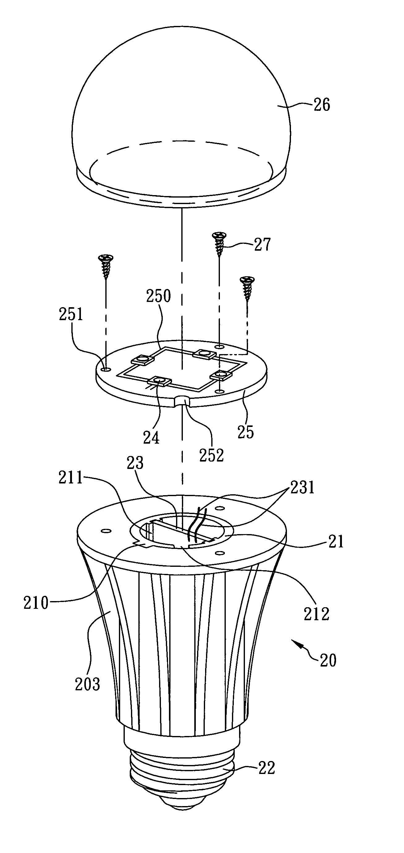
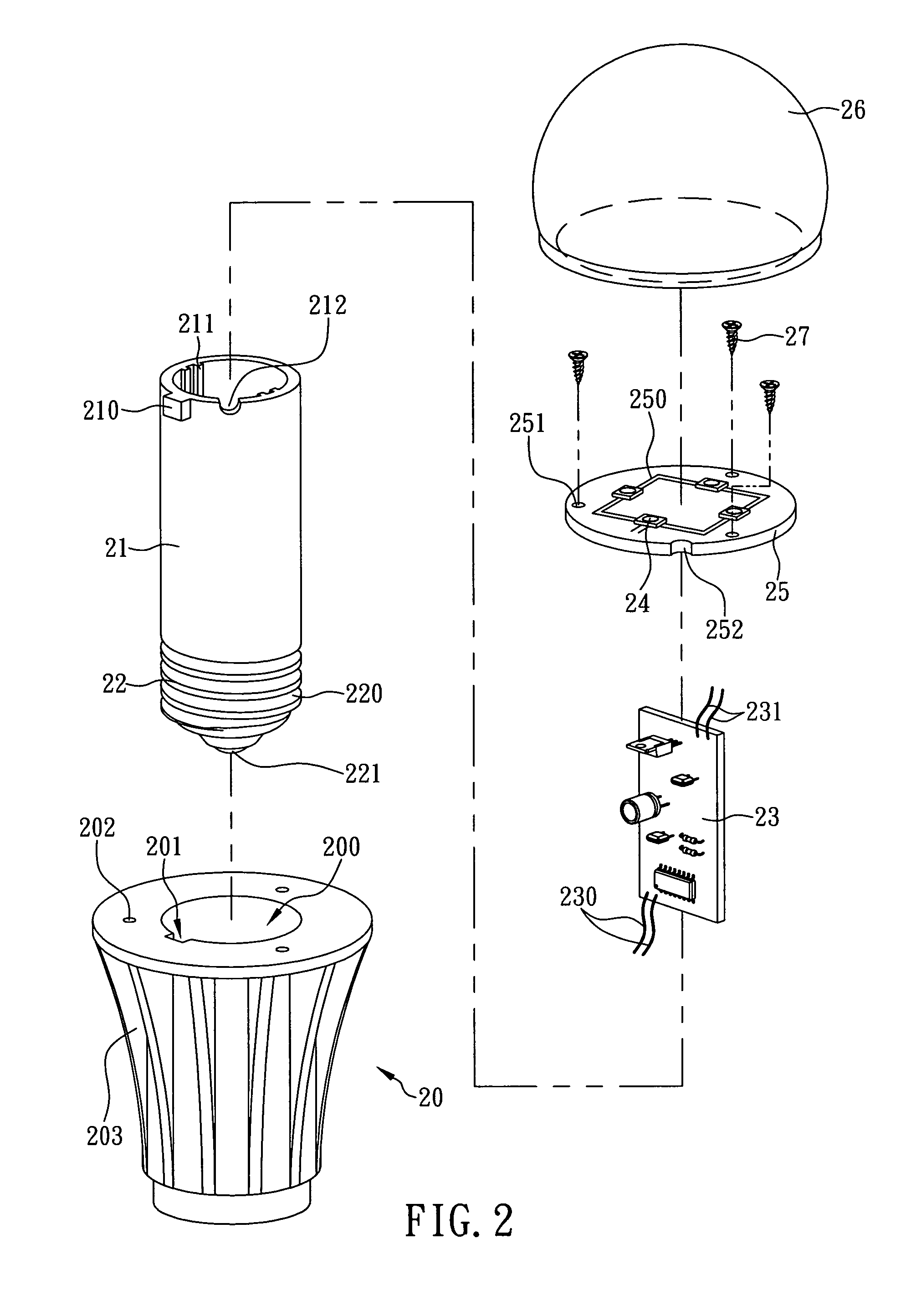
[0015]The present invention is related to an LED (light emitting diode) lamp. Referring now to FIG. 2, an LED lamp according to a preferred embodiment of the present invention is illustrated. As shown, the LED lamp comprises a heat dissipation housing 20, an insulation housing 21, an electrode cap 22, a power printed circuit board (PCB) 23, at least one LED 24, an installation base plate 25 and a lamp shade 26, wherein the heat dissipation housing 20 is a housing made of aluminum alloy or ceramic material. If the heat dissipation housing 20 is made of aluminum alloy, an outer periphery of the heat dissipation housing 20 is preferably extended outward to form a plurality of cooling fins 203, in order to increase the heat dissipation surface area of the heat dissipation housing 20 and enhance the heat dissipation efficiency of the heat dissipation housing 20. Alternatively, if the heat dissipation housing 20 is made of ceramic material, the structure design of the cooling fins 203 on ...


PUM


Abstract

The present invention is to provide an LED lamp, which comprises a heat dissipation housing formed with a receiving hole axially passed therethrough, an insulation housing, an electrode cap connected to the insulation housing, a power PCB, and an installation base plate having a first side installed with at least one LED. A manufacturer only needs to firstly insert the insulation housing along with the electrode cap into the receiving hole for allowing the electrode cap to be extended out of a lower end of the heat dissipation housing, then insert the power PCB into the insulation housing and electrically connect the power PCB to the electrode cap, and finally position a second side of the installation base plate on the upper end of the heat dissipation housing and electrically connect the installation base plate to the power PCB, so as to rapidly complete the installation of the LED lamp.

Description

FIELD OF THE INVENTION[0001]The present invention relates to an LED (light emitting diode) lamp, more particularly to an LED lamp having an electrode cap connected to an insulation housing thereof, so that a manufacturer only needs to firstly insert the insulation housing along with the electrode cap into a heat dissipation housing of the LED lamp and then rapidly completes the installation of the LED lamp.BACKGROUND OF THE INVENTION[0002]In the past, people use incandescent lamps for night or indoor illumination because the incandescent lamps can provide some advantages including simple installation. However, since the incandescent lamps also have some disadvantages including high power consumption, short lamp life (average life of only about 1,000 hours) etc., more and more users change to use energy-saving fluorescent lamps about ten years ago based on demands of environmental protection and energy saving. The so-called “fluorescent lamp” is an integral illumination apparatus con...

Claims


Application Information

Patent Timeline
Patent Type & Authority Patents(United States)
IPC IPC(8): H01J1/02
CPCF21K9/1355F21V3/00F21V19/0055F21V29/507F21V29/773F21V29/86F21V23/002F21Y2101/02F21K9/23F21Y2115/10
Inventor LIANG, JIM-HUNG
Owner SKYNET ELECTRONICS
Why Eureka
Try Eureka