Inductive conductivity sensor

a conductivity sensor and conductivity technology, applied in the direction of transformers/inductance coils/windings/connections, instruments, material impedances, etc., can solve the problems of increasing the total structural size the cross sectional area of the passageway cannot be arbitrarily increased, etc., to simplify the automation of manufacture and small axial length of the conductivity sensor

Inactive Publication Date: 2011-06-21
ENDRESS HAUSER CONDUCTA GESELLSCHAFT FUER MESS UND REGELTECHNIK MBH CO KG
View PDF25 Cites 27 Cited by
  • Summary
  • Abstract
  • Description
  • Claims
  • Application Information

AI Technical Summary

Benefits of technology

[0005]To this end, the invention provides an inductive conductivity sensor with a new type of coil construction, which makes possible an especially small axial length for the conductivity sensor. According to a further point of view of the invention, the new type of coil construction enables a simplified automated manufacture.

Problems solved by technology

The cross sectional area of the passageway can, however, not be arbitrarily increased for a given manner of coil construction, without increasing the total structural size of the conductivity sensor.

Method used


Image

  • Inductive conductivity sensor
  • Inductive conductivity sensor
  • Inductive conductivity sensor

Examples


Embodiment Construction

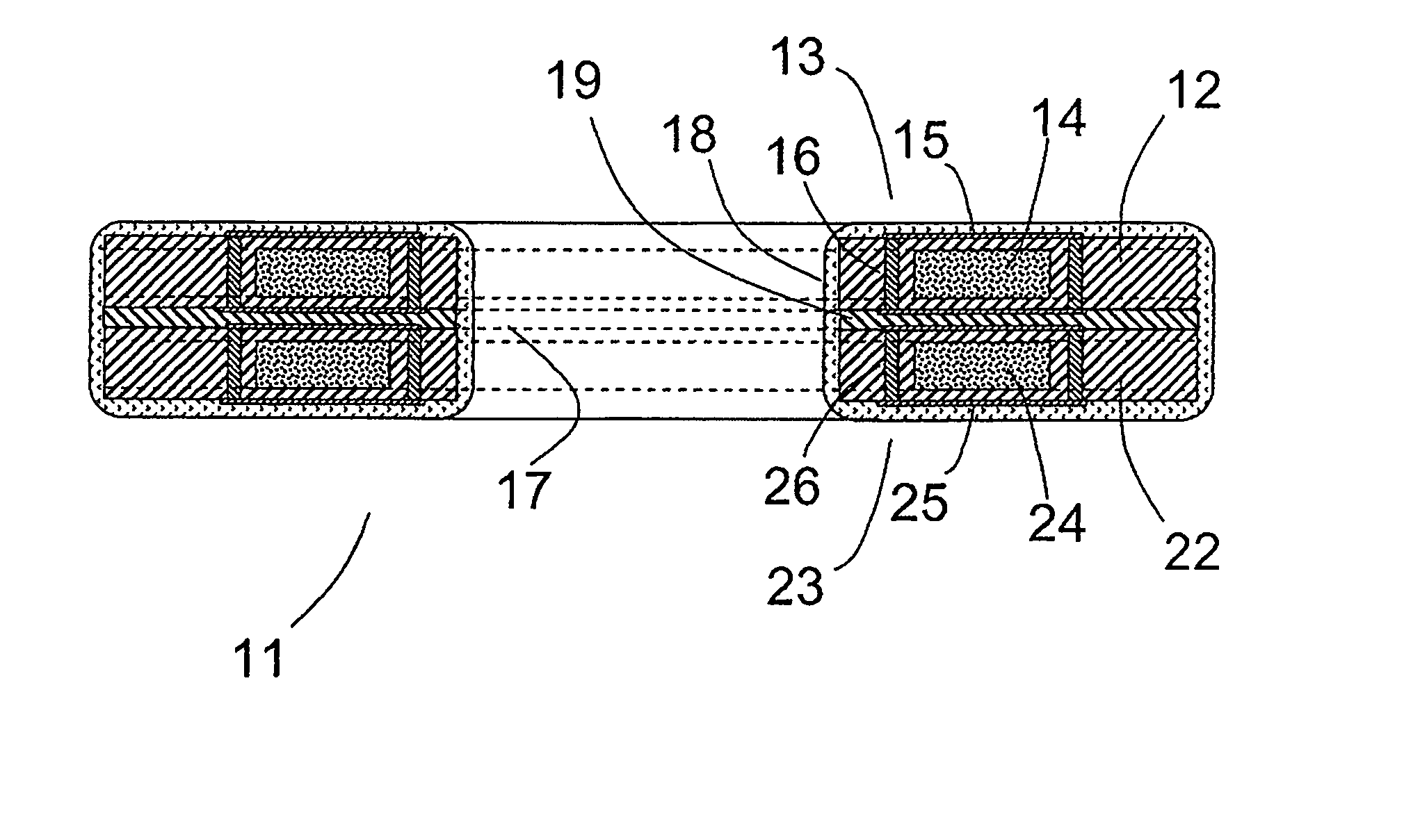
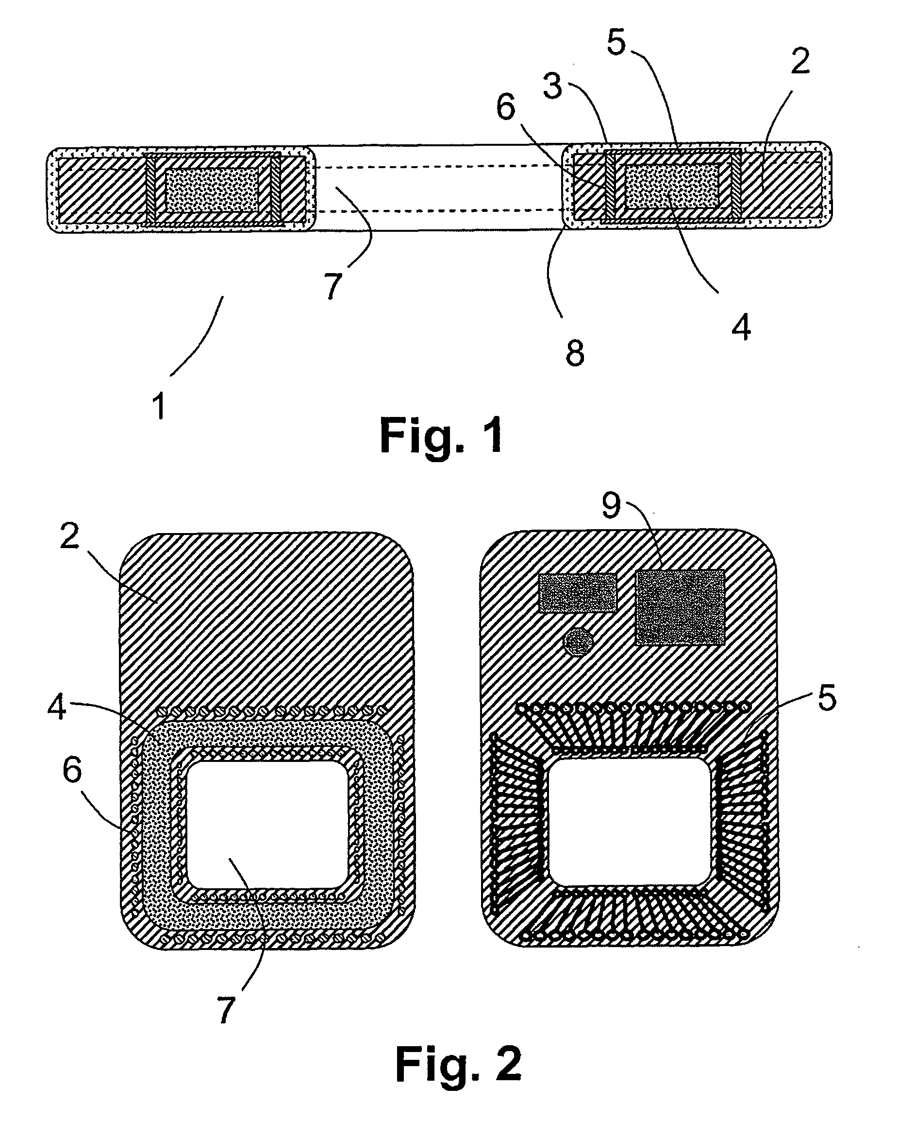
[0021]FIG. 1 shows a longitudinal section of a coil arrangement 1 for a conductivity sensor in a multi-ply circuit board 2. A view of different plies of this multi-ply circuit board 2 of the coil arrangement is shown in FIG. 2, wherein the left portion of the figure shows an intermediate ply and the right portion a cover ply. The coil arrangement will now be explained with reference to FIGS. 1 and 2.

[0022]Coil arrangement 1 includes a toroidal coil 3, which annularly bounds a passageway 7 in the circuit board 2. The toroidal coil 3 includes first conductor segments 5, which extend on the upper side of the cover ply, and second conductor segments, which extend on the underside of a base ply of the circuit board. Between the base ply and the cover ply, an intermediate ply is arranged, which itself can include one or more plies. The intermediate ply includes a cavity in which a tape-based ring-core 4 for the toroidal coil 3 can be placed, before the cover ply is joined with the interme...


PUM

PropertyMeasurementUnit
conductivityaaaaaaaaaa
electrical currentaaaaaaaaaa
magnetic fieldaaaaaaaaaa

Abstract

A conductivity sensor for measuring conductivity of a medium surrounding the conductivity sensor includes a first toroidal coil bounding a medium-receiving passageway and serving for inducing an electrical current in the medium, and a second toroidal coil also bounding the passageway and serving for registering a magnetic field produced by the electrical current. At least one of the toroidal coils has a plurality of first conductor segments, which extend in a plane of a multi-ply circuit board, a plurality of second conductor segments, which extend in a second plane of the circuit board, and a plurality of through-contacts, which connect the first conductor segments with the second conductor segments, wherein the first conductor segments, the second conductor segments and the through-contacts form, together, the windings of a toroidal coil.

Description

[0001]This application is a Nonprovisional Application which claims the benefit of U.S. Provisional Application Ser. No. 60 / 924,775 filed on May 31, 2007.TECHNICAL FIELD[0002]The present invention relates to an inductive conductivity sensor.BACKGROUND DISCUSSION[0003]Inductive conductivity sensors for ascertaining electrical conductivity of a medium include, essentially, two toroidal coils, surrounded by the medium. The coils bound a passageway for the medium and are usually arranged coaxially, with a first of the coils, as exciter coil, inducing an electrical current in the medium. Such electrical current is then registered by the second coil. The principle, per se, is established in industrial process measurements technology and documented in a large number of examples of the patent literature, for example in U.S. Pat. No. 3,603,873 and German Offenlegungsschrift DE 198 51 146 A1.SUMMARY OF THE INVENTION[0004]An object of the invention is to provide an inductive conductivity senso...

Claims


Application Information

Patent Timeline
Patent Type & Authority Patents(United States)
IPC IPC(8): H01F27/28
CPCG01N27/025
Inventor VÖLKER, MARCOEBERHEIM, ANDREASPECHSTEIN, TORSTEN
Owner ENDRESS HAUSER CONDUCTA GESELLSCHAFT FUER MESS UND REGELTECHNIK MBH CO KG
Why Eureka
Try Eureka