Coefficient of thermal expansion control structure

a control structure and thermal expansion technology, applied in the direction of electrical/magnetic/electromagnetic heating, couplings, manufacturing tools, etc., can solve the problems of dimensional mismatch, dimensional mismatch, and difficulty in maintaining dimensional accuracy, so as to reduce the thickness of the face-sheet, reduce the thermal expansion of composite tooling, and constrain the diametric growth of the tooling

Active Publication Date: 2011-06-28
THE BOEING CO
View PDF19 Cites 11 Cited by
  • Summary
  • Abstract
  • Description
  • Claims
  • Application Information

AI Technical Summary

Benefits of technology

[0010]The present invention is directed to a system and method for reducing thermal expansion of composite tooling. This system and method preferably comprises incorporating substructure into the composite tooling to constrain diametric growth of the tooling during manufacturing. Embodiments of the substructure incorporated into the tooling preferably include the addition of headers and gussets, reducing the thickness of the face-sheet of the tooling, and / or introducing inner skin into the tooling.
[0011]Additional embodiments of the present invention are directed to methods for controlling thermal expansion of a mandrel. This method preferably comprises adding substructure to the mandrel to limit hat wall rotation of the mandrel. Other embodiments of the present invention include incorporating into the mandrel combinations of headers and gussets forming all or a portion of the substructure. In a further embodiment of the present invention, the thickness of a constrained face-sheet of the mandrel may be reduced in order to further reduce thermal expansion of the mandrel. Additional embodiments include incorporating inner skin into the mandrel.

Problems solved by technology

However, this commonality of CTEs is not always practically achievable.
A mismatch in the CTEs of the part and the tooling used to form the part will often result in complications for maintaining dimensional accuracy.
This discrepancy in the contraction and expansion due to cooling typically causes the part to experience dimensional mismatches due to the residual thermal loading effect.
However, problems occur upon cooling the mandrel and the part.
Once the combination is cooled, the resultant structure of the part is still smooth (i.e., had little to no visible wrinkling), however, the part experiences undesirable sagging, for example, from the mandrel.
This wrinkling typically results because parts cured on invar tooling may not grow enough to eliminate the bulk factor wrinkles.
Furthermore, the growth required that shims were needed to hold the part in place during the trimming process.
Accordingly, it was determined that use of traditional carbon / epoxy mandrels produced good quality laminates; however the final skin shape may not be as desirable because the radius and circumferential dimensions of the part formed may be too large for use in one-piece barrel aerospace applications.
However, modifying the size of the tool was not preferable as the expansion of the tool affects the dimensions and overall shape of the part being formed.

Method used


Image

  • Coefficient of thermal expansion control structure
  • Coefficient of thermal expansion control structure
  • Coefficient of thermal expansion control structure

Examples


embodiment a

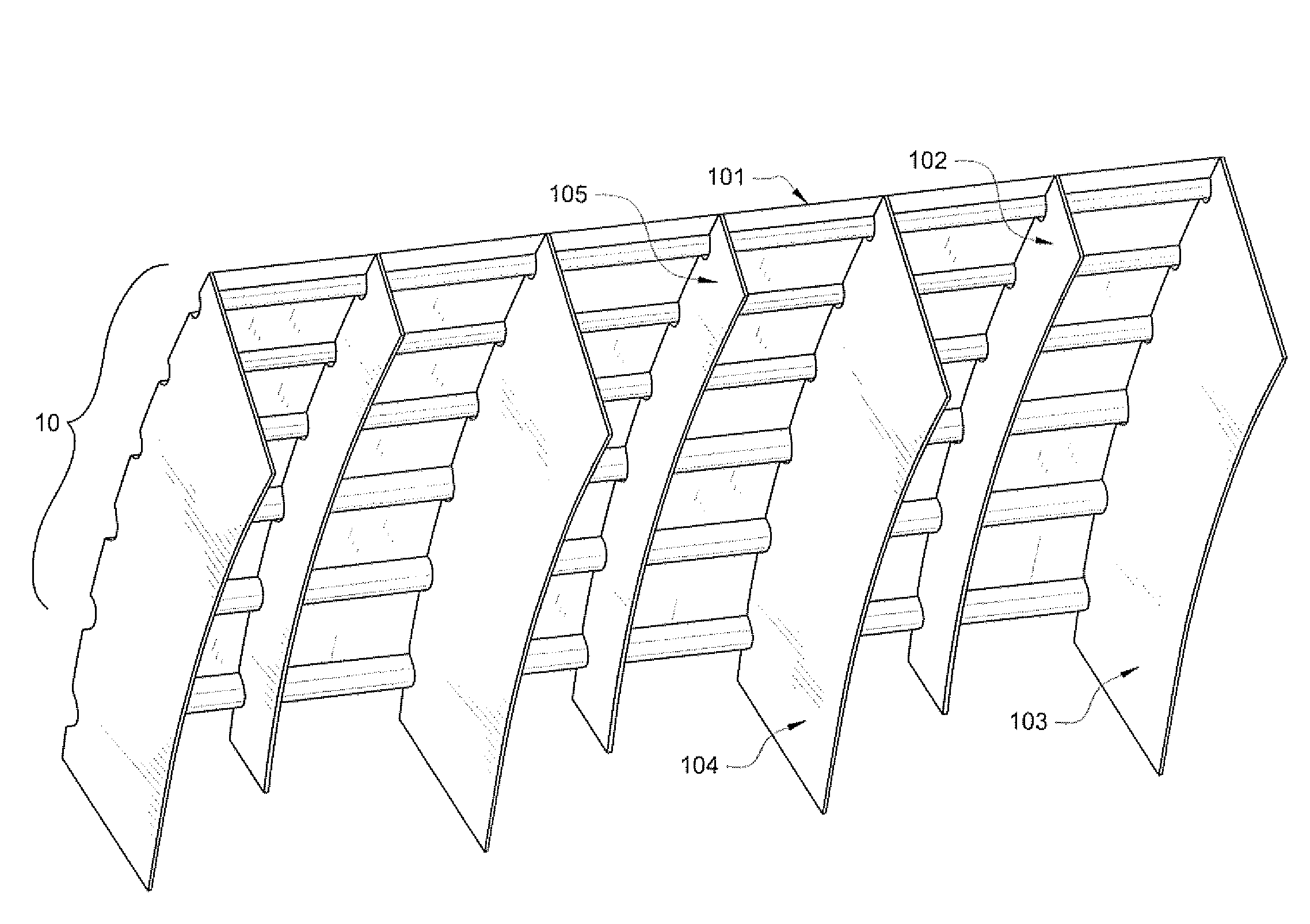
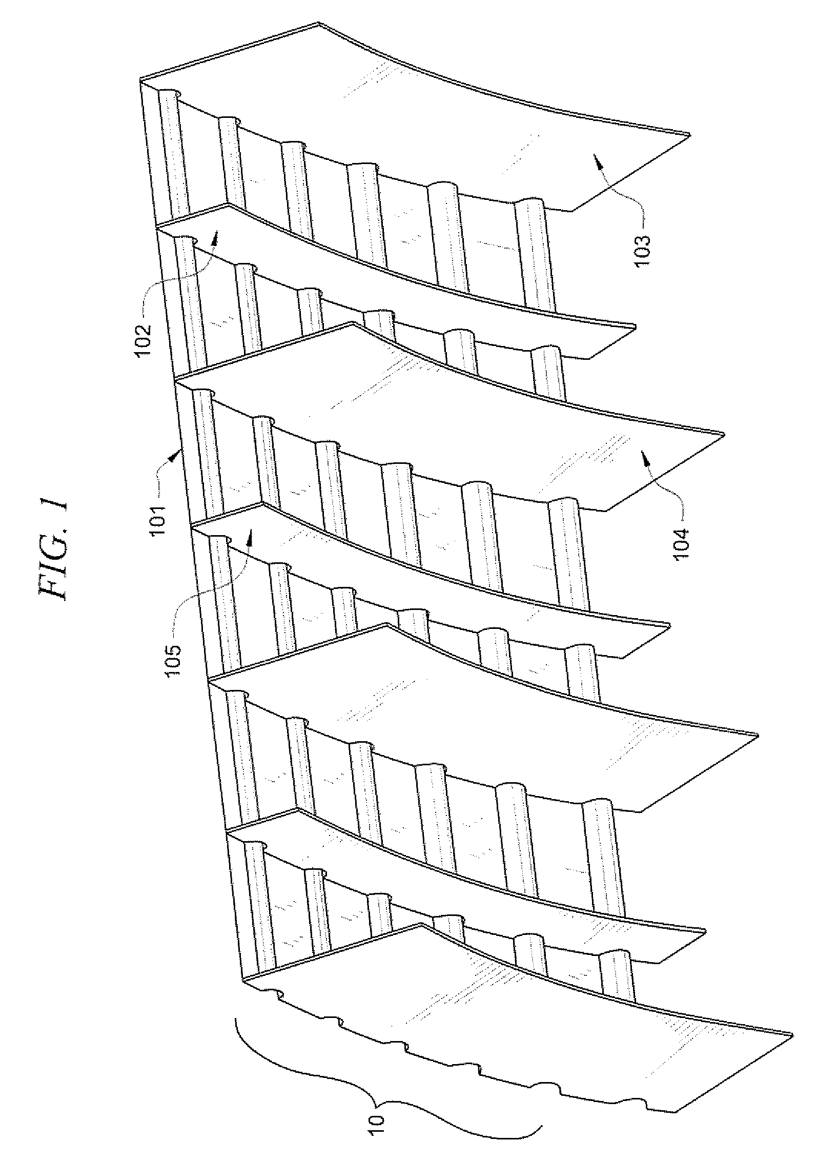
[0032]In an embodiment of the present invention, the face-sheet thickness of the mandrel prior to any modifications or addition of substructure was 0.75 in. The face-sheet thickness was then modified and reduced by approximately one-half to a thickness of 0.375 in. In this embodiment, headers (such as headers 103, 104 depicted in FIG. 1) are incorporated as part of the mandrel substructure. The spacing between the headers was originally 36 in. However, the header spacing is preferably modified and reduced by one-third to a distance of 24 in. between headers. By reducing the face-sheet thickness in conjunction with reducing the distance of the header spacing, the effective CTE is preferably reduced from approximately 8.7×10⁻⁶ in. / in. ° F. to approximately 3.1×10⁻⁶ in. / in. ° F. Accordingly, the effective CTE may preferably be reduced by over 50% based on modifying the header spacing and thinning the face-sheet of the mandrel.

embodiment b

[0033]In a further embodiment of the present invention, headers (such as headers 103i, 104 depicted in FIG. 1) are preferably incorporated into the mandrel. Gussets (such as gussets 102, 105 depicted in FIG. 1) measuring approximately 2 in. tall are then preferably added between the headers. Inclusion of the headers as well as the gussets preferably achieves an effective CTE of approximately 3.0×10⁻⁶ in. / in. ° F. This effective CTE is essentially equivalent to that achieved by reducing the face-sheet thickness and header spacing as discussed previously with respect to Embodiment A.

embodiment c

[0034]In yet another embodiment of the present invention, similar to Embodiments A and B, headers (such as headers 103. 104 depicted in FIG. 1) are preferably incorporated as part of the substructure of the mandrel. Also, similar to Embodiment B, gussets (such as gussets 102, 105 depicted in FIG. 1) are preferably added between the headers of the mandrel. However, in this embodiment, gussets taller than those utilized in Embodiment B are incorporated as part of the substructure of the mandrel. In an embodiment of the invention the 2 in. tall gussets of Embodiment B are replaced with 6 in. tall gussets. By incorporating taller gussets into the substructure of the mandrel, the effective CTE may preferably be further reduced to approximately 2.8×10⁻⁶ in. / in. ° F.


PUM

PropertyMeasurementUnit
thermal expansionaaaaaaaaaa
coefficient of thermal expansionaaaaaaaaaa
CTEaaaaaaaaaa

Abstract

The present invention is directed to the incorporation of a substructure into tooling for constructing composite structures in order to control thermal expansion of the tooling during aerospace manufacturing processes. Substructure, such as headers and / or gussets is added to the tooling to constrain the growth of the laminate expansion and / or control the diametric growth of the tool during the curing cycle. The thickness of the face-sheet of the tooling also may be reduced in order to further reduce the effective coefficient of thermal expansion (CTE) of the tooling.

Description

TECHNICAL FIELD[0001]The present invention relates to controlling thermal expansion of a tool during a manufacturing process, and more specifically, to reducing the effective coefficient for thermal expansion for mandrels during an aerospace manufacturing process.BACKGROUND OF THE INVENTION[0002]It is commonly known that materials expand and contract with changes in temperature. A commonly used quantifier of this natural phenomenon is the coefficient of thermal expansion or CTE. Generally, CTE can be thought of as a ratio of the change in length of a line segment in a body per unit of temperature change to its length at a reference temperature. When a material is heated, its linear dimensions increase approximately in proportion to the temperature. Over moderate changes in temperature, the length of a material changes by an amount:ΔL=Lo α(ΔT)where Δ (delta) indicates “change in”, T is temperature (in degrees Fahrenheit), and L is length (in inches). The constant α is called the coef...

Claims


Application Information

Patent Timeline
Patent Type & Authority Patents(United States)
IPC IPC(8): F16D1/00
CPCB29C70/44B29D99/0014B29C70/46
Inventor CLEARY, JR., WILLIAM RUSSELLLITAKER, CASEY GRANTNEWKIRK, TODD LELANDDOYON, JOSHUA JOSEPH
Owner THE BOEING CO
Why Eureka
Try Eureka