Miniaturized optical tweezers based on high-NA micro-mirrors

a micro-mirror and optical tweezers technology, applied in the field of micro-meter-sized dielectric particles, can solve the problems of not showing multiple traps and probably not being able to generate such a system

Active Publication Date: 2011-06-28
ECOLE POLYTECHNIQUE FEDERALE DE LAUSANNE (EPFL)
View PDF14 Cites 19 Cited by
  • Summary
  • Abstract
  • Description
  • Claims
  • Application Information

AI Technical Summary

Benefits of technology

[0020]Miniaturizing such micro-mirrors and arranging them in two dimensional arrays allows creating virtually unlimitedly large optical traps arrays that could be integrated in more complex micro-devices, including micro-fluidic devices.
[0022]Three dimensional trapping, miniaturization, massive parallelism, and highly-efficient light-signals collection make the present invention an ideal solution for integrating arrays of optical traps into advanced bio-analytical miniaturized systems.

Problems solved by technology

Multiple traps were not demonstrated and probably cannot be generated with such a system.

Method used


Image

  • Miniaturized optical tweezers based on high-NA micro-mirrors
  • Miniaturized optical tweezers based on high-NA micro-mirrors
  • Miniaturized optical tweezers based on high-NA micro-mirrors

Examples


Embodiment Construction

6.1 Micro-mirrors as High-NA Micro-optical Components

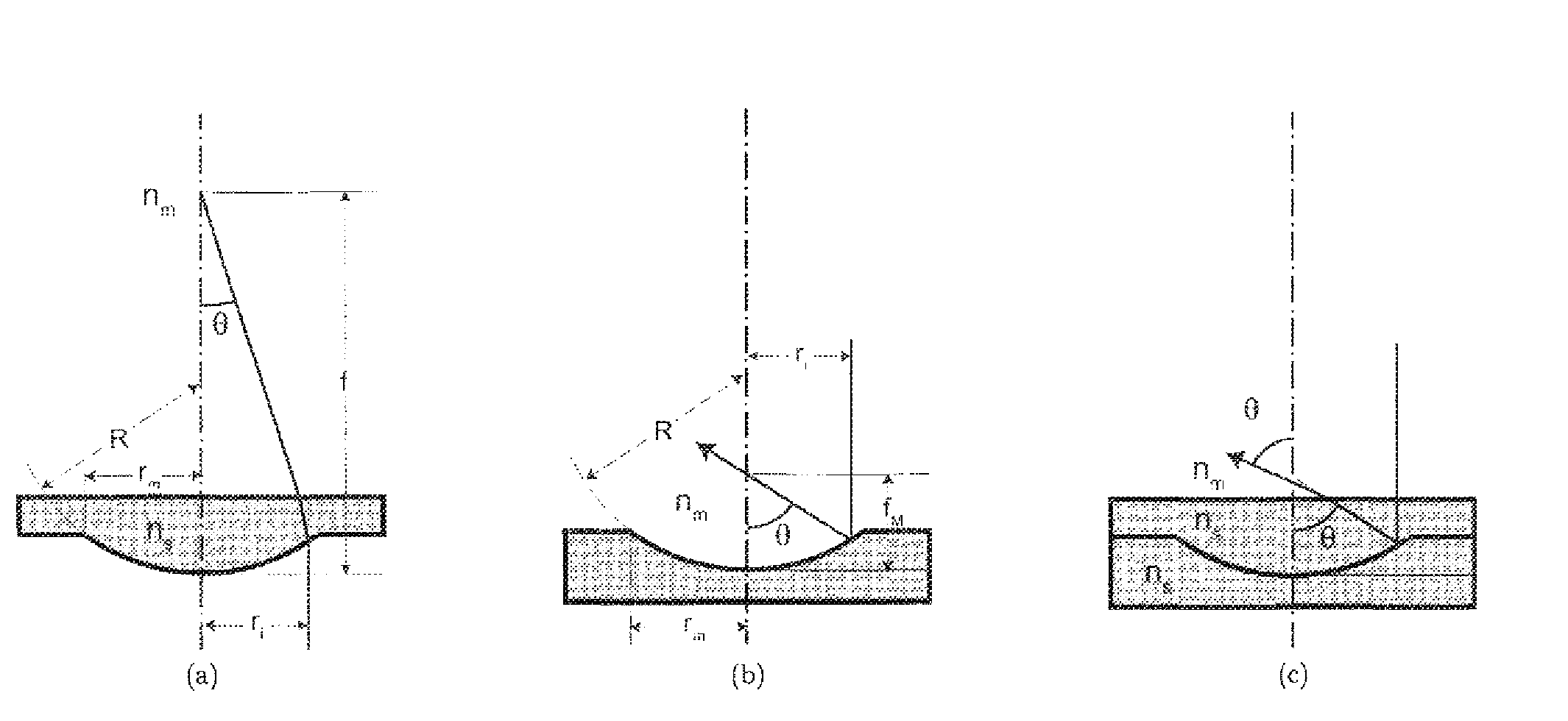
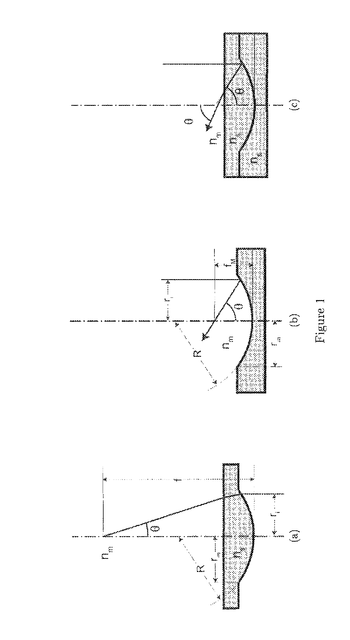
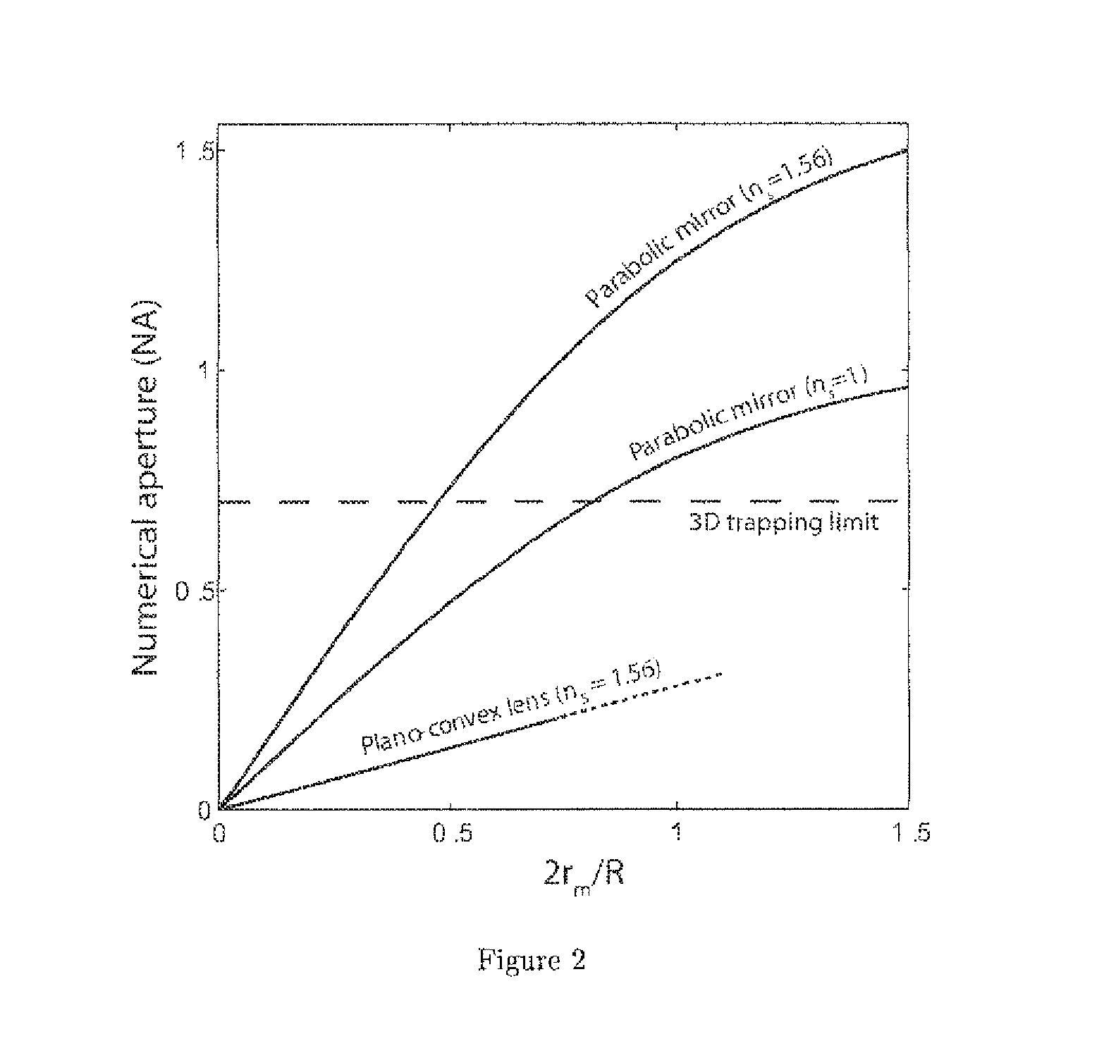
[0033]The core of the present invention lies in the use of reflective instead of refractive or diffractive micro-optical components. While refractive and diffractive focusing micro-optical components can only achieve relatively limited numerical apertures (typically NA<0.5), reflective focusing micro-mirrors easily allow reaching very high NAs.

[0034]The micro-mirror arrays as defined in a preferred embodiment of the present invention should not be confused with electrostatically actuated micro-mirror arrays (also known as digital micro-mirror devices, DMDs). Electrostatically actuated micro-mirror arrays are composed of a matrix of flat, independently actuated tilting micro-mirrors. These are typically employed for spatially and temporally modulating a light source. In contrast, the invention embodiment below describes a fixed array of concave micro-mirrors, each micro-mirror being employed for focusing a portion of an incident el...


PUM

PropertyMeasurementUnit
diameteraaaaaaaaaa
sizesaaaaaaaaaa
refractive indexaaaaaaaaaa

Abstract

The invention relates to an optical tweezer device including at least one light source and one three-dimensional optical trap, said optical trap comprising one focusing micro-mirror which is adapted to reflect and focus at least a portion of the light emitted by said light source.

Description

[0001]This application is the U.S. national phase of International Application No. PCT / IB2007 / 052955 filed 25 Jul. 2007 which designated the U.S. and claims priority to International Application No. PCT / IB2006 / 052567 filed 26 Jul. 2006, the entire contents of each of which are hereby incorporated by reference.1 TECHNICAL FIELD[0002]The present invention relates to trapping of micrometer-sized dielectric particles, including biological particles, using electromagnetic fields created by strongly focused light.2 BACKGROUND OF THE INVENTION[0003]In 1970, Arthur Ashkin [1] demonstrated how milliwatts of laser radiation can be used to accelerate end even trap micron-sized particles suspended in liquid and gas. Historically, the first laser trap was relying on two counter-propagating laser beams. Later, Ashkin [2] demonstrated that by focusing a single laser beam very tightly, transparent dielectric particles characterized by a refractive index higher than the refractive index of the surro...

Claims


Application Information

Patent Timeline
Patent Type & Authority Patents(United States)
IPC IPC(8): H01S3/00C12M3/00
CPCG21K1/006
Inventor MERENDA, FABRICEROHNER, JOHANNSALATHE, RENE
Owner ECOLE POLYTECHNIQUE FEDERALE DE LAUSANNE (EPFL)
Why Eureka
Try Eureka