Laser direct imaging apparatus

a direct imaging and laser technology, applied in lasers, laser details, instruments, etc., can solve the problem of limited variety of workpieces to which can be exposed

Active Publication Date: 2011-06-28
ADTEC ENG
View PDF3 Cites 24 Cited by
  • Summary
  • Abstract
  • Description
  • Claims
  • Application Information

AI Technical Summary

Benefits of technology

[0013]An object of the present invention is to solve the foregoing problem. Another object of the present invention is to provide a laser direct imaging apparatus which can expose photosensitive materials having various sensitivities and which can correct an imaging position in accordance with deformation of a workpiece.
[0016]The angle (scanning angle α) of the cylindrical axis of the cylindrical lens with respect to the main scanning direction can be set easier. Accordingly, photosensitive materials having various sensitivities can be exposed.

Problems solved by technology

Accordingly, the range of possible scanning angle α is so narrow that the workpieces which can be exposed are limited in variety.

Method used


Image

  • Laser direct imaging apparatus
  • Laser direct imaging apparatus
  • Laser direct imaging apparatus

Examples


Embodiment Construction

[0026]The present invention will be described below with reference to the drawings.

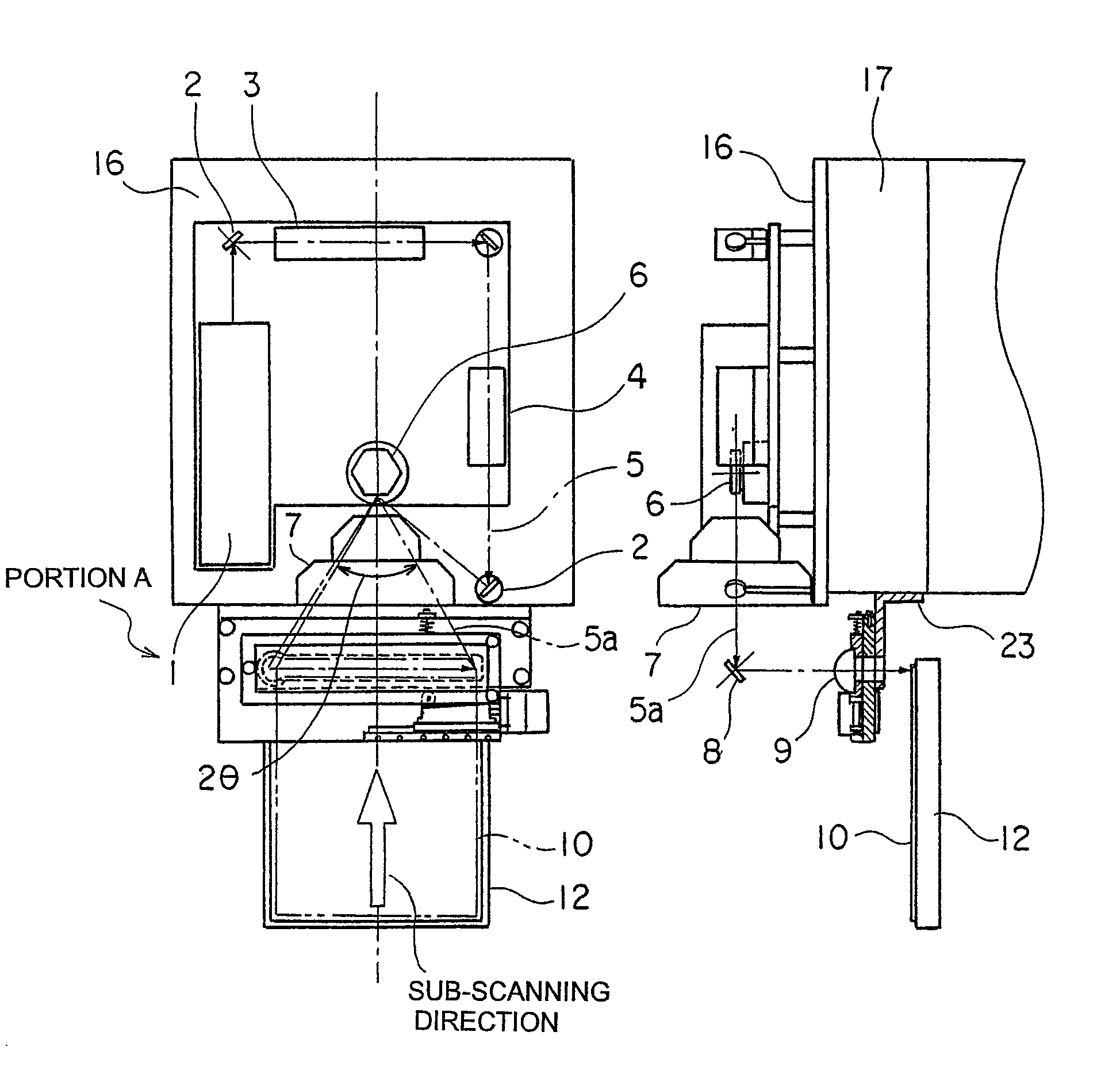
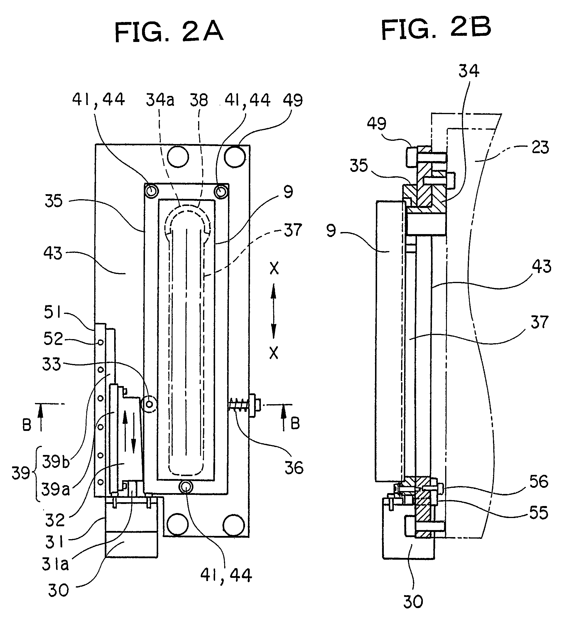
[0027]FIGS. 1A and 1B are views showing a configuration of a laser direct imaging apparatus according to the present invention. FIG. 1A is a plan view, and FIG. 1B is a side view. FIGS. 2A and 2B are enlarged fragmentary view of a portion A in FIG. 1A. FIG. 2A is a plan view, and FIG. 2B is a side view. For convenience of representation, FIGS. 2A and 2B show the state where the same as that in FIGS. 1A and 1B has been rotated at an angle of 90°. FIG. 3 is a fragmentary sectional view of the vicinities of a pin 44 which will be described later. FIG. 4 is a sectional view taken on the line B-B in FIG. 2A. Parts the same as or having the same functions as those in FIG. 7 are designated with the same reference numeral and a description thereof is omitted.

[0028]A bracket 23 is fixed to a column 17. A base plate 43 is fixed onto the bracket 23 by bolts 49. A hollow hinge pin 34 has a hollow horseshoe boss p...


PUM


Abstract

A laser direct imaging apparatus which can expose photosensitive materials having various sensitivities and which can correct an imaging position in accordance with deformation of a workpiece. In the laser direct imaging apparatus, the workpiece is moved in a sub-scanning direction while a cylindrical lens is used to converge a laser beam, which has been modulated based on raster data, in the sub-scanning direction and deflect the laser beam toward a main scanning direction so as to image a desired pattern on the workpiece. The cylindrical axis of the cylindrical lens is designed to be able to rotate horizontally and to be able to change an angle with respect to the main scanning direction.

Description

FIELD OF THE INVENTION[0001]The present invention relates to a laser direct imaging (LDI) apparatus for moving a workpiece in a sub-scanning direction while using a cylindrical lens to condense a laser beam, which has been modulated based on raster data, in the sub-scanning direction and deflect the laser beam toward a main scanning direction so as to image a desired pattern on the workpiece.BACKGROUND OF THE INVENTION[0002]In an LDI apparatus, CAD data used for designing a circuit pattern are converted into vector data format, and then contours are calculated from the vector data. After that, the contours are further converted into raster data for imaging. From the raster data, ON and OFF pixels for a laser beam are obtained. The ON pixels are irradiated with the laser beam.[0003]FIG. 7 is a view showing a configuration of background-art LDI apparatus.[0004]A laser source 1 is mounted on an optical table 16. The optical table 16 is disposed on a column 17 on a bed 18. A laser beam ...

Claims


Application Information

Patent Timeline
Patent Type & Authority Patents(United States)
IPC IPC(8): G02B26/08
CPCG03F7/70383G03F7/2006H01S3/10
Inventor NAITO, YOSHITATSUOSHIDA, YOSHITADASUZUKI, MITSUHIRO
Owner ADTEC ENG
Why Eureka
Try Eureka