Diversity receiver

a receiver and diversity technology, applied in the field of diversity reception, can solve the problems of limiting the output power of the transmitter station, requiring a rerouted feeder cable, and no pictures and sounds at all, and achieve the effect of high diversity gain

Inactive Publication Date: 2011-06-28
MITSUBISHI ELECTRIC CORP
View PDF16 Cites 48 Cited by
  • Summary
  • Abstract
  • Description
  • Claims
  • Application Information

AI Technical Summary

Benefits of technology

[0013]The present invention is made to solve such problems as described above, and an object of the invention is to provide a diversity receiver that is incorporated in a television with a plurality of built-in antennas for easy installation in a room and is capable of enhancing its diversity gain.
[0015]According to the present invention, a diversity receiver is provided with a plurality of first variable gain amplifiers corresponding to a plurality of first antennas as well as with a plurality of second variable gain amplifiers corresponding to a plurality of second antennas, and is configured to control directions of directional radiation patterns each formed by the first antennas and the second antennas. Therefore, a high diversity gain can be obtained even when these antennas built into a television are arranged in close vicinity to each other.

Problems solved by technology

For that reason, when moving a television to be located to another room, a problem arises in that it takes an effort to re-route the feeder cable having been routed.
A problem arises in that, if such a strength level cannot be ensured, no pictures and no sounds are reproduced at all.
Moreover, in a terrestrial digital broadcasting system, all the carriers within the bandwidth (5.6 MHz) must be received and a transmitter station is restricted in its output power.
Accordingly, in a case of an antenna being mounted in a bad condition, there has been a problem in that it is not easy to ensure a reception signal more than a certain level of strength by the antenna.
On the other hand, when antennas are built into a television, it is hard to ensure a sufficient distance between the antennas.
Accordingly, there has been a problem in obtaining a high diversity gain.
Moreover, when antennas are built into a television, even though the antennas each are arranged on television cabinet surfaces orthogonal to each other to apply a scheme that selects a larger level signal from those received by the antennas, only a contribution from either one of the antennas is obtained, which has caused a problem that only a low diversity gain is expected.
For that reason, there has been a problem in applying the method to a stationary television whose direction is not easily adjusted due to it being located in a room, whereas there arises no problem for the case with the mobile phone because a viewer can readily vary the direction of its antennas with the phone held by hand.

Method used


Image

  • Diversity receiver
  • Diversity receiver
  • Diversity receiver

Examples


embodiment 1

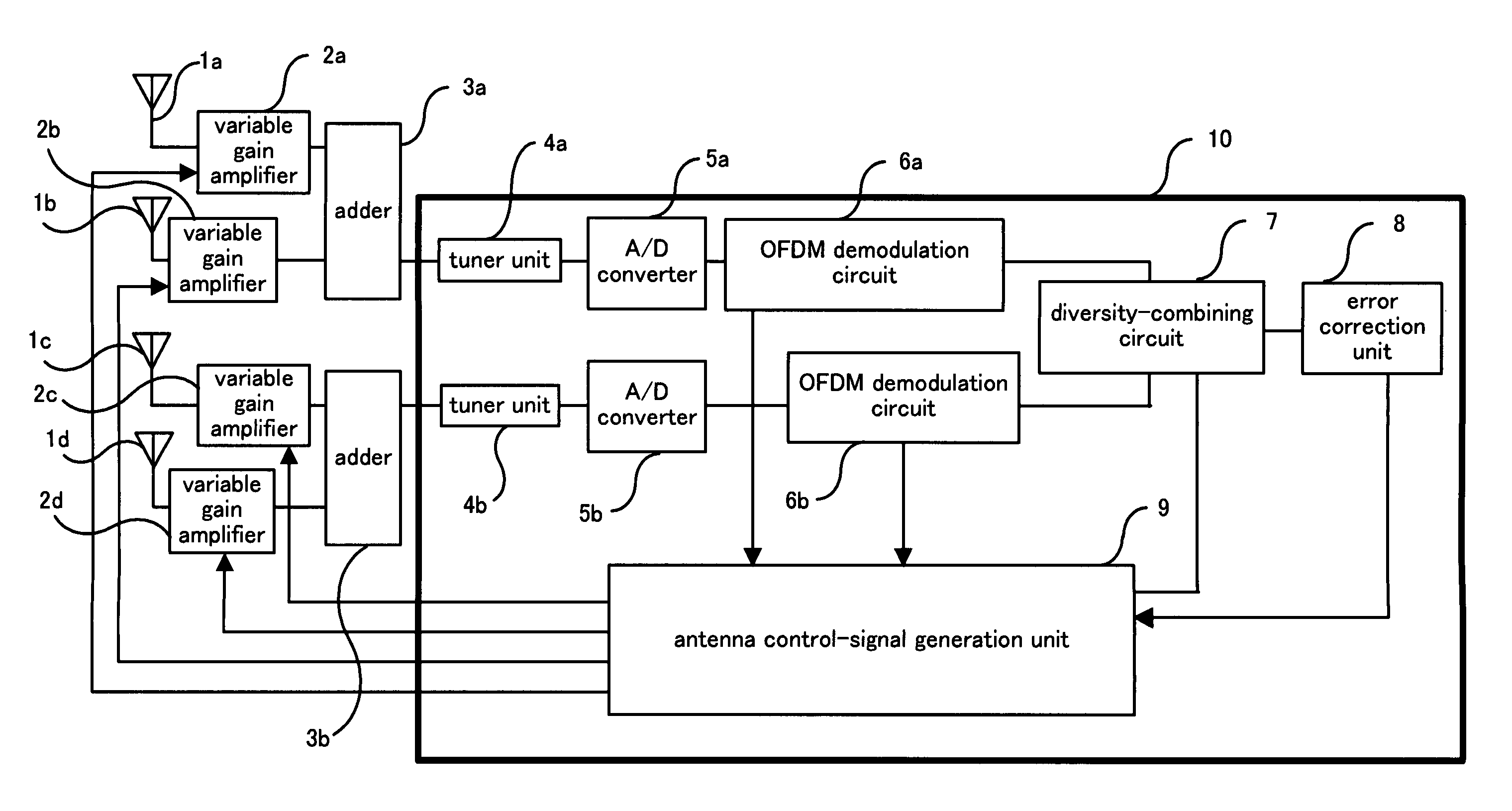
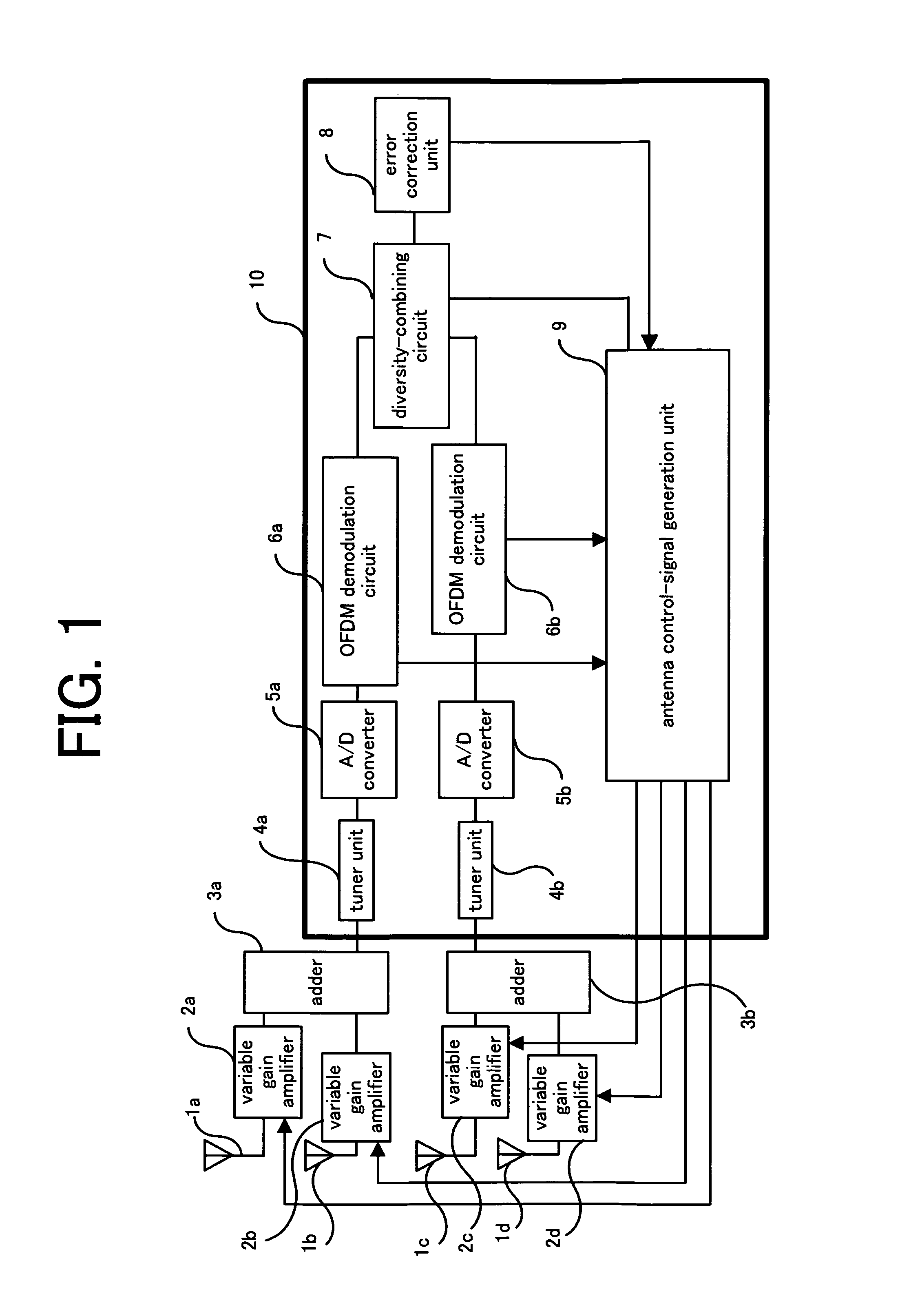
[0037]FIG. 1 is a diagram illustrating an overall configuration of a diversity receiver according to Embodiment 1 of the present invention.

[0038]Referring to FIG. 1, antennas 1a and 1b, which are a plurality of first antennas that receive terrestrial digital broadcast radio waves, are connected to variable gain amplifiers 2a and 2b, respectively, for varying gains of the antennas. The antennas 1a and 1b are such dipole-antennas or pole-antennas that have a figure-eight directional radiation pattern, to have a sufficient reception sensitivity for terrestrial digital broadcast radio waves coming from two directions opposite to each other. The variable gain amplifiers 2a and 2b include attenuators, for example, composed of pin-diodes.

[0039]Incidentally, radio waves broadcast from terrestrial digital broadcast stations are basically polarized horizontally whereas vertical polarized components may sometimes be produced under the influences of electromagnetic environments such as building...

embodiment 2

[0088]While in Embodiment 1 of the invention a diversity receiver has been explained on the case of the antennas having a figure-eight directional radiation pattern, directional antennas having only one direction of radiation pattern may be used.

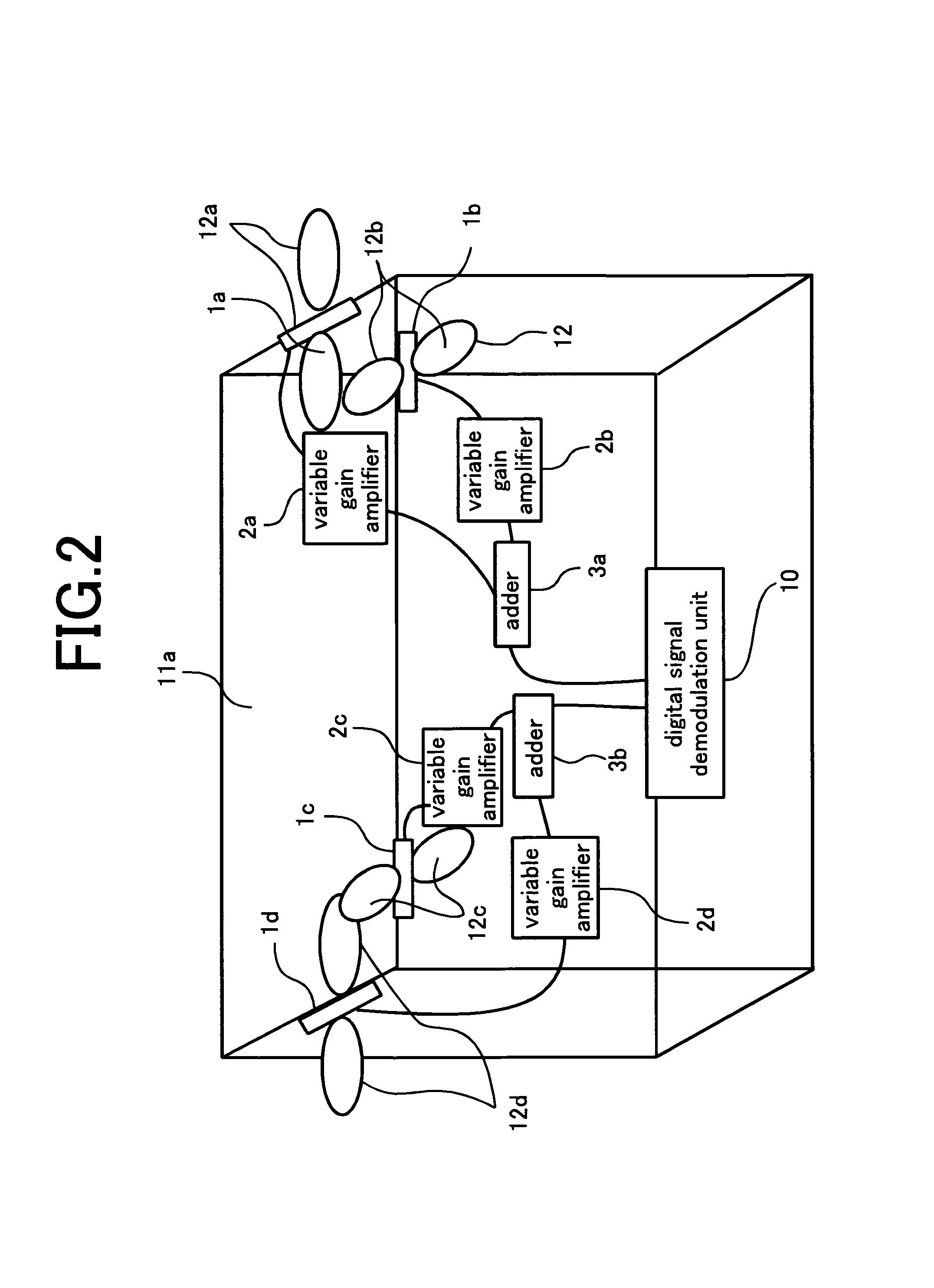
[0089]FIG. 7 is a perspective view seen from the rear of a television, and illustrates a configuration example of a diversity receiver incorporated in the television in a case of using directional antennas, according to Embodiment 2 of the invention. In addition, since the same reference numerals as those in FIGS. 1 and 2 denote the same or equivalent components, their explanations will be omitted.

[0090]As shown in FIG. 7, seen from the rear of the television, an antenna 1e of a first branch is arranged on the right lateral side of the television such that its directional radiation pattern 12e is oriented in the right direction in FIG. 7. Accordingly, for a terrestrial digital broadcast radio wave propagating from the right to the left on FI...

embodiment 3

[0100]In Embodiment 1 and Embodiment 2 of the invention, a diversity receiver has a plurality of branches configured with variable gain amplifiers that control gains of a plurality of respective antennas and with adders that add outputs of each variable gain amplifiers so as to diversity-combine demodulated signals of the branches. In Embodiment 3, a diversity receiver has a branch, instead of a branch configured with variable gain amplifiers and an adder, configured with phase combiners that combine received signals of a plurality of antennas with a fixed phase to output a plurality of phase-combined signals and configured with a selection circuit that selects one phase-combined signal from the plurality of phase-combined signals. That configuration can also enhance gains after the diversity combining and bring about a stable reception.

[0101]FIG. 9 is a diagram illustrating an overall configuration of the diversity receiver according to Embodiment 3 of the invention. In addition, s...


PUM


Abstract

A diversity receiver is provided with antennas (1a) and (1b) in a first branch and antennas (1c) and (1d) in a second branch each of which antenna gains is controlled so that the offset between the directions of directional radiation patterns for the first and second branches becomes approximately π / 2. Thereby, the diversity receiver can obtain a sufficient diversity gain even when it is incorporated into an indoor television with the antennas being built thereinto in close vicinity to one another.

Description

TECHNICAL FIELD[0001]The present invention relates to diversity reception for a digital-communication receiver or a digital-broadcast receiver, more particularly to a diversity receiver that receives terrestrial digital-broadcasts through antennas built into a television or the like.BACKGROUND OF THE INVENTION[0002]When receiving digital broadcasts on a television located in a room using an antenna mounted outdoors, a feeder cable is necessarily routed from the antenna to the television. For that reason, when moving a television to be located to another room, a problem arises in that it takes an effort to re-route the feeder cable having been routed.[0003]Hence, instead of using an antenna mounted outdoors, an indoor antenna has been used or a rod antenna has been built into a television itself.[0004]To watch digital broadcasts, however, a reception signal received by an antenna is needed to exceed a certain level of strength. A problem arises in that, if such a strength level canno...

Claims


Application Information

Patent Timeline
Patent Type & Authority Patents(United States)
IPC IPC(8): G06F3/033
CPCH01Q3/24H01Q3/28H01Q3/30H01Q21/20H04N21/6112H04B7/0868H04N5/4401H04N21/4263H04B7/0848H04N21/426
Inventor ARITA, EIJIIDO, JUNMAENO, AKIKO
Owner MITSUBISHI ELECTRIC CORP
Why Eureka
Try Eureka