

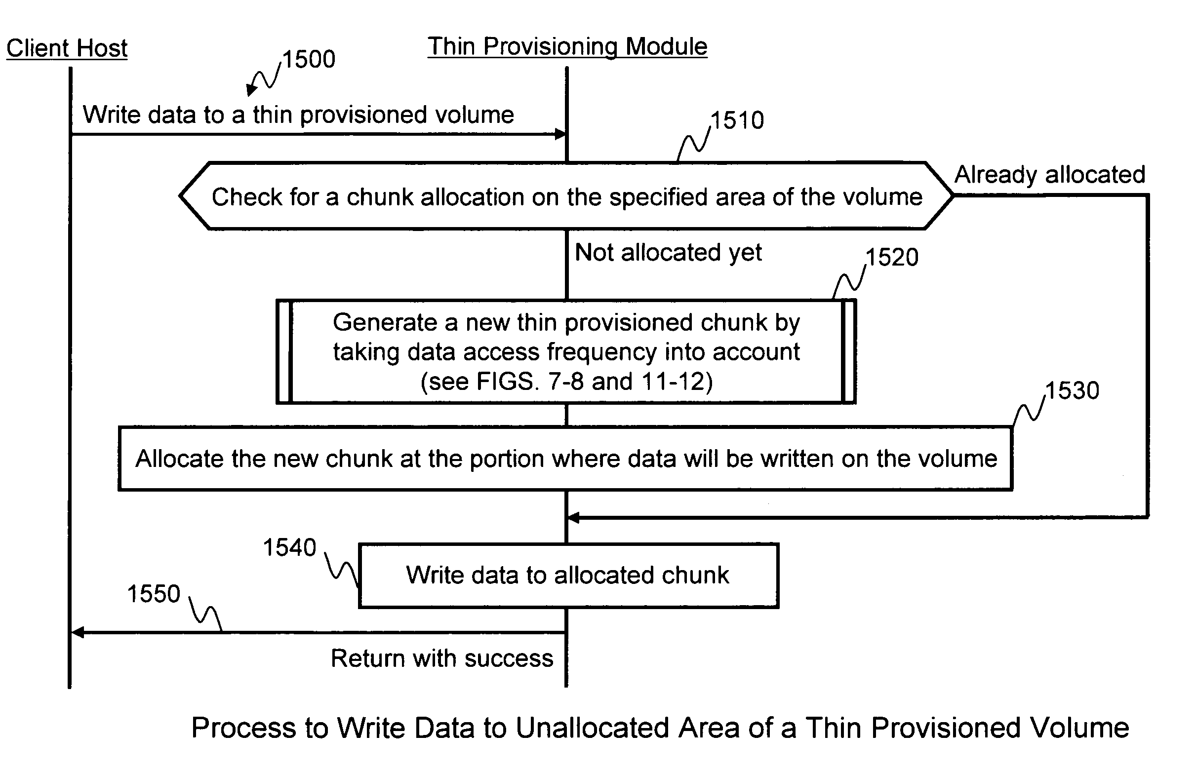
Method and apparatus for chunk allocation in a thin provisioning storage system
a storage system and chunk allocation technology, applied in the field of storage systems for storing data, can solve the problems of increasing the capacity of hard disk drives, the performance of these drives, and the speed of data writing and retrieval cannot keep up with the increase in capacity, so as to maintain the efficiency of disk capacity utilization and eliminate performance bottlenecks.
- Summary
- Abstract
- Description
- Claims
- Application Information
AI Technical Summary
Benefits of technology
Problems solved by technology
Method used
Image

Examples
first embodiments
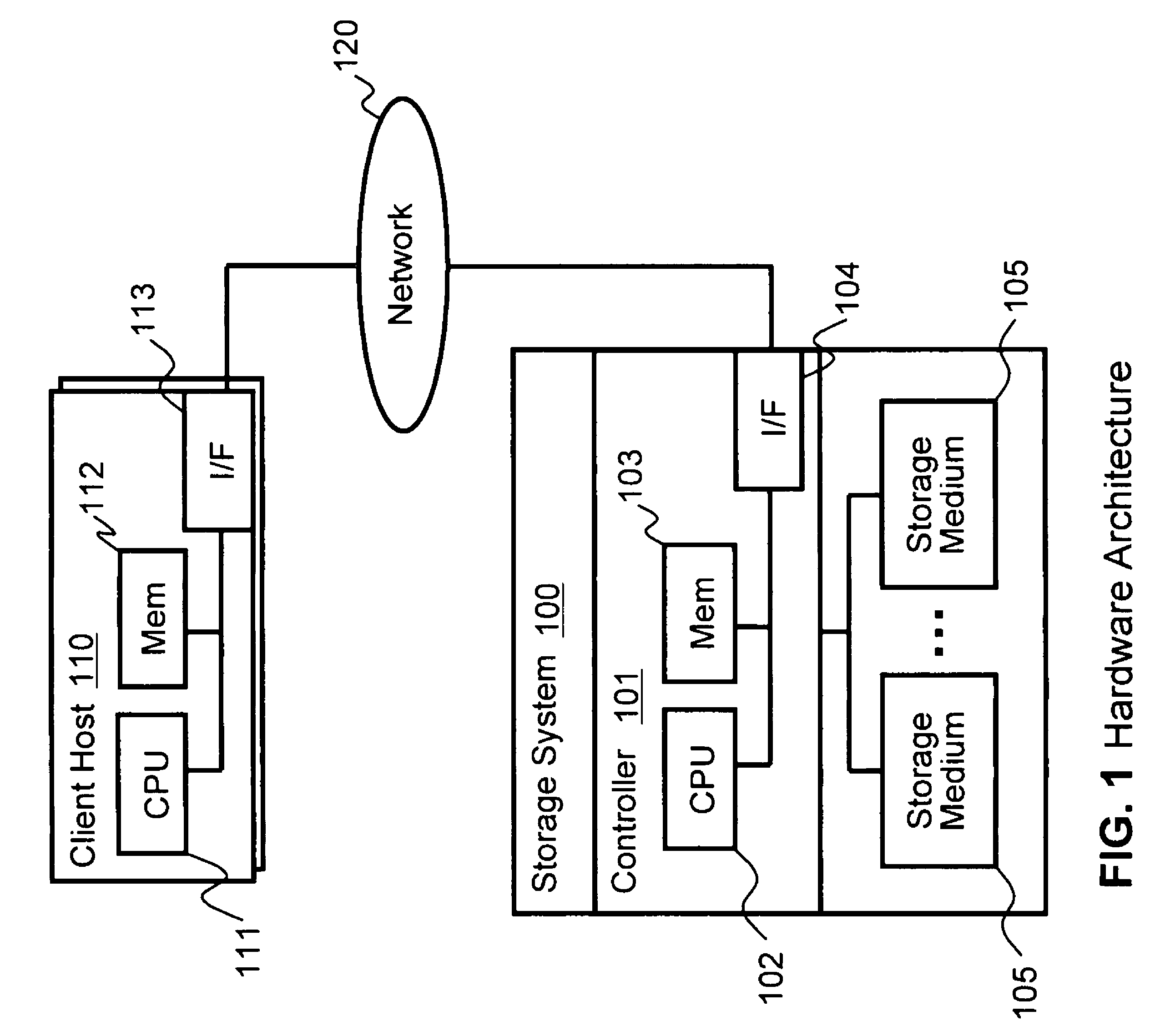
FIG. 1 illustrates an example of a physical hardware architecture that may be used to implement some embodiments of the invention. The overall system consists of a storage system 100 and one or more client hosts 110. Client hosts 110 and storage system 100 are connected through a network 120. Network 120 may be any variety of network type, such as Ethernet, Fibre Channel (FC), or the like.
Storage system 100 includes a controller 101 and storage mediums 105. Controller 101 includes a CPU 102, a memory 103, and a network interface (I / F) 104. Storage mediums 105 are connected to controller 101 through a local bus, FC connection, or the like. Storage mediums 105 are hard disk drives in the preferred embodiment, but in some embodiments may be any of a variety or combination of other storage devices such as, flash memory, optical disks, tape, and so on. Each client host 110 may be a computer that includes a CPU 111, a memory 112, and a network interface 113 for communicating with storage ...
second embodiments
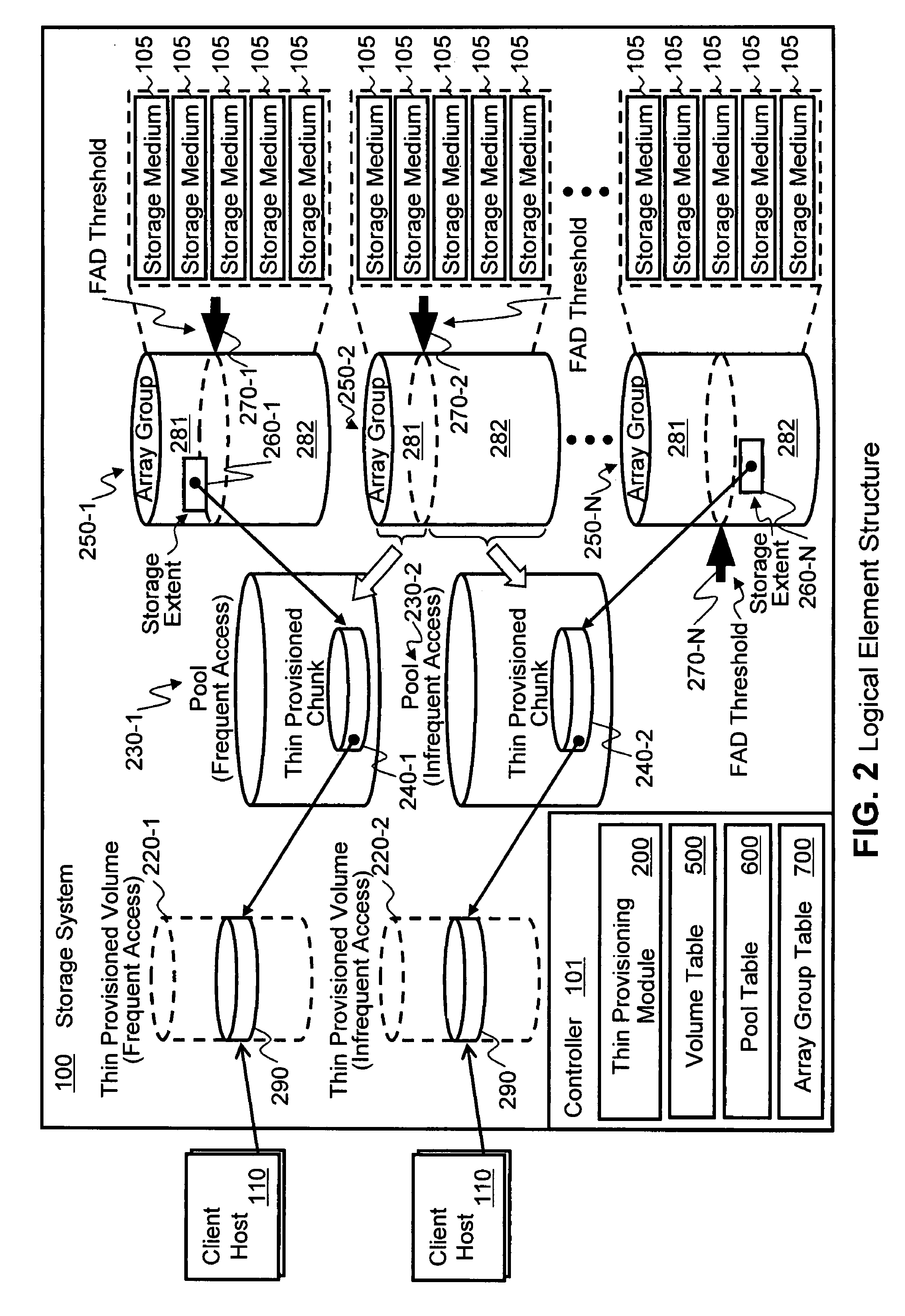
In the first embodiments described above, threshold or capacity boundary 270 of the frequent access data for respective array groups 250 is a fixed value which has been predefined. However it may be difficult for an administrator to determine the threshold before actually using the devices with a certain amount of frequent access data stored on them. For example, a certain desired performance level might not actually be achieved at the predefined threshold set by the administrator, or the predefined threshold might be placed too conservatively, thereby wasting capacity that could otherwise be allocated for frequent access data. Accordingly, the second embodiments of the invention include a method to determine the threshold dynamically in an automated manner based on a performance metric of each array group. By providing the automated feature of the invention for determination of the threshold, the administrator does not have to struggle to define the threshold. Furthermore, the thre...
PUM
 Abstract
Description
Claims
Application Information