Labyrinth seal

a technology of seals and spherical layers, applied in the field of spherical layers, can solve the problems of high pressure fluid moving across the sealing surface, reducing the life of the seal assembly, and becoming very costly to stop the operation of the engine for unnecessary inspection and/or repair, etc., and achieve the effect of reducing leakag

Inactive Publication Date: 2011-07-05
FLORIDA TURBINE TECH
View PDF16 Cites 31 Cited by
  • Summary
  • Abstract
  • Description
  • Claims
  • Application Information

AI Technical Summary

Benefits of technology

[0014]The present invention is a stepped labyrinth seal with a vortex generating curved rib extending in the cavity between adjacent teeth, the curved ribs acting to redirect a portion of the leakage air flow back toward the upstream gap for the particular cavity and thus creating a vortex flow in the cavity. The vortex flow generating ribs accelerate the vortex flow toward and against the in-coming leakage air and thus producing a leakage inhibiting counter flow affect. As a result of this secondary flow interaction, a reduction in leakage is achieved across the labyrinth seal. The counter flow affect will continue throughout the entire labyrinth seal stage.

Problems solved by technology

Also, excess hot gas flow across the blade tip can cause thermal damage to the labyrinth seal, resulting in the life of the seal assembly to be reduced.
In an industrial gas turbine engine, it becomes very costly to stop operation of the engine for unnecessary inspection and / or repairs due to worn parts.
In this fashion, high pressure fluid moving across the sealing surface will encounter interference; thus, minimizing leakage.

Method used


Image

  • Labyrinth seal
  • Labyrinth seal
  • Labyrinth seal

Examples


Embodiment Construction

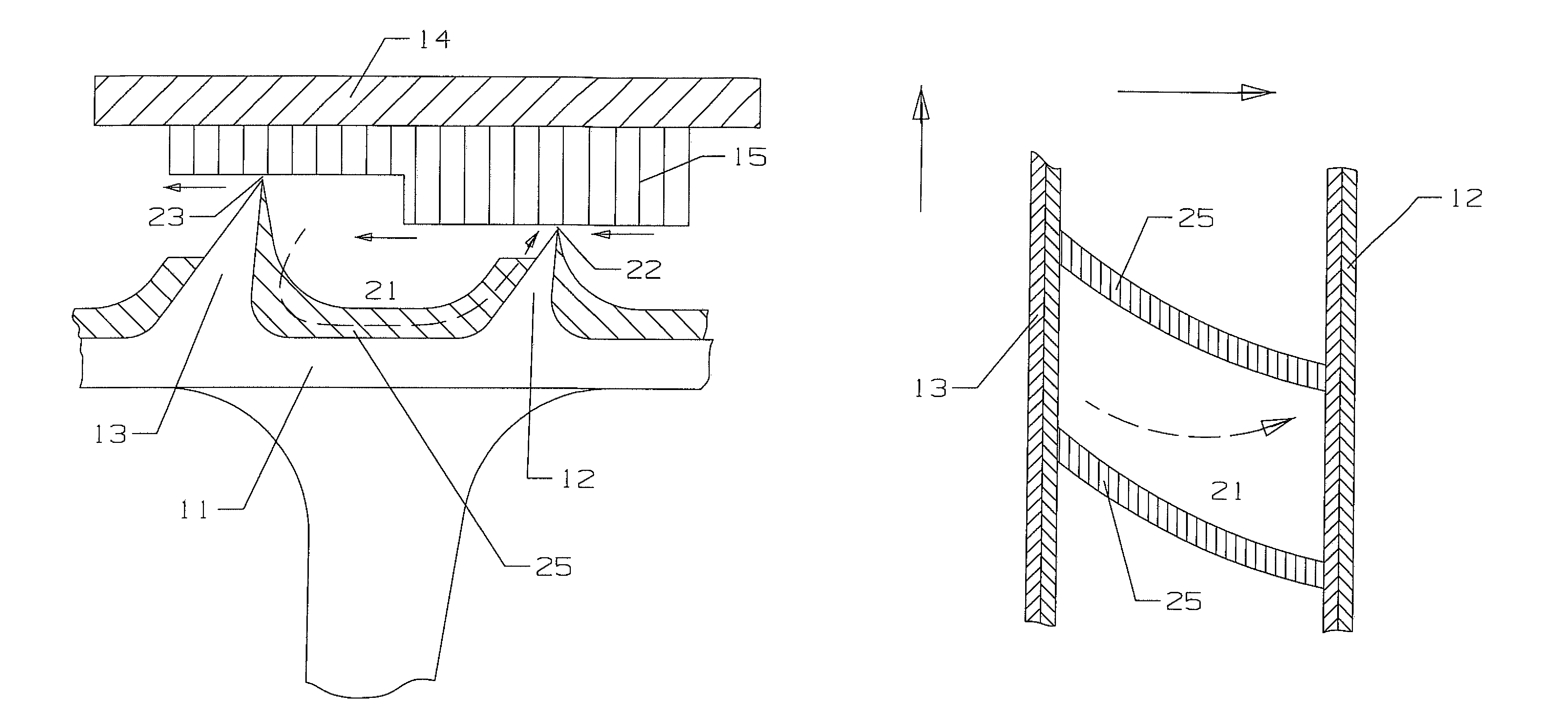
[0018]The present invention is a labyrinth seal for use in a gas turbine engine, in which the labyrinth seal is formed between a rotating blade tip and a stationary honeycomb surface of the engine. However, the invention is a stepped labyrinth seal which could be used in any apparatus having a seal formed between a rotating member and a stationary member.

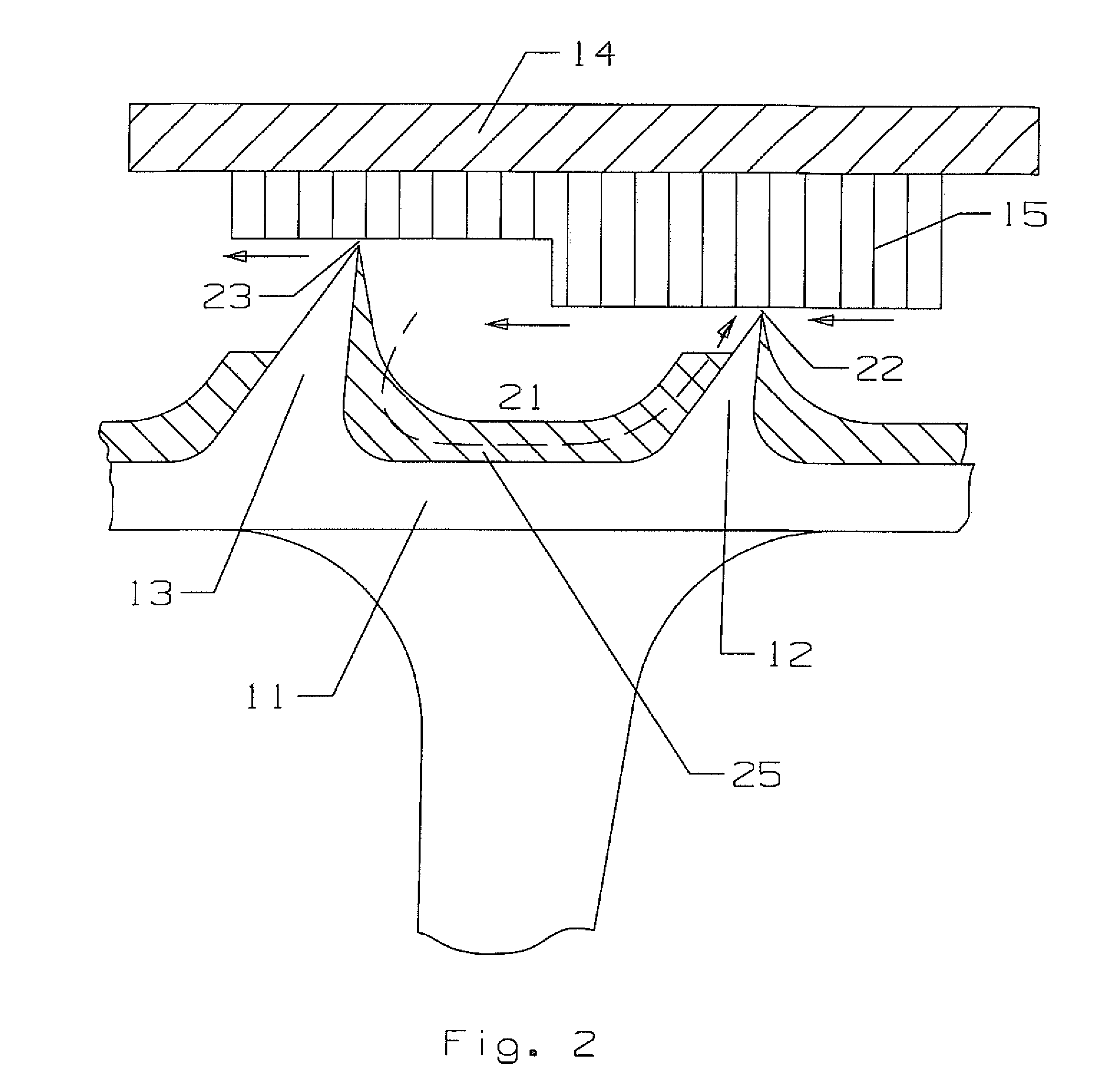
[0019]FIG. 2 shows a stepped labyrinth seal having teeth (an upstream tooth 12 and a downstream tooth 13) extending from a rotating member 11, the teeth being angled in a direction toward the upstream side of the leakage flow. A honeycomb surface 15 secured to the stationary member 14 includes the stepped surface that forms two gaps (upstream gap 22 and downstream gap 23) for the leakage to flow across from the upstream gap 22 to the downstream gap 23. A cavity 21 or chamber is formed between the adjacent teeth 12 and 13 with a floor on the rotating member. Extending across the cavity between adjacent teeth is a row of vortex genera...


PUM


Abstract

A stepped labyrinth seal having a plurality of teeth forming gaps between a stationary honeycomb member, where the cavities formed between adjacent teeth include a plurality of vortex flow generating strips on the wall of the cavity that redirect the leakage flow from a gap back toward the gap and in a direction toward the gap in order to limit the leakage flow through the gap. The vortex generating strips extend along the cavity floor and up the sides of the teeth forming the cavity. The strips slope downward from the downstream tooth toward the upstream tooth in the direction of rotation, and with a curvature in the direction of rotation. The stepped labyrinth seal is intended for use in a gas turbine engine having a plurality of stages in the turbine, with the labyrinth seal being used to seal the gap between rotating blades and the honeycomb surface on the stationary casing.

Description

GOVERNMENT LICENSE RIGHTS[0001]None.CROSS-REFERENCE TO RELATED APPLICATIONS[0002]This application is a CONTINUATION of U.S. patent application Ser. No. 11 / 654,127 filed on Jan. 17, 2007 and entitled LABYRINTH SEAL AND PROCESS FOR REDUCING LEAKAGE IN A LABYRINTH SEAL.BACKGROUND OF THE INVENTION[0003]1. Field of the Invention[0004]The present invention relates generally to a labyrinth seal, and more specifically to a honeycomb seal used in a gas turbine engine.[0005]2. Description of the Related Art including information disclosed under 37 CFR 1.97 and 1.98[0006]Honeycomb seals are used in gas turbine engines such as those used to power an aircraft or a marine craft, or to produce electrical power. A gas turbine engine includes a turbine section that converts the energy in a hot gas flow passing through the turbine into mechanical work to drive the rotor shaft. The rotor shaft drivers the compressor and, in the case of an industrial gas turbine, drives the electric generator. The turb...

Claims


Application Information

Patent Timeline
Patent Type & Authority Patents(United States)
IPC IPC(8): F16J15/447
CPCF01D11/02F16J15/444F05D2240/127
Inventor LIANG, GEORGE
Owner FLORIDA TURBINE TECH
Why Eureka
Try Eureka