Burner for the operation of a heat generator and method of use

a heat generator and burner technology, applied in the direction of lighting and heating apparatus, combustion types, combustion using lumps and pulverizing fuel, etc., can solve the problems of unstable, high stress, high cost, etc., and achieve low pollutant value, avoid overheating of components, and stable operation

Active Publication Date: 2011-07-05
GENERAL ELECTRIC TECH GMBH
View PDF27 Cites 6 Cited by
  • Summary
  • Abstract
  • Description
  • Claims
  • Application Information

AI Technical Summary

Benefits of technology

[0015]One of numerous aspects of the present invention includes an improved burner which can be operated with liquid fuel in pilot mode. In particular, stable operation with low pollutant values can be achieved, as well as avoidance of overheating of components. Furthermore, a construction which is modularized as far as possible can be provided, which for example allows replacement of the elements of the pilot burner. Specifically, it concerns the improvement of a burner for operating a heat generator in this case, wherein the burner comprises a swirler for a combustion air flow, and also means for injecting at least one fuel into the combustion air flow, wherein a mixing path is arranged downstream of the swirler, and wherein at least one nozzle for feeding liquid pilot fuel is arranged in the region radially outside the discharge opening of the mixing path of the burner. In principle, therefore, it concerns a burner of the type as is described in EP 0 321 809 B1, wherein in addition, as this is described for example in EP 0 704 657 B1 or in EP 0 780 629 B1, transfer passages can be arranged between the swirler and the mixing path.
[0016]Another aspect of the present invention includes the at least one nozzle being arranged in a burner front plate, wherein in a front face of the burner front plate, which is arranged essentially parallel to a combustion chamber rear wall, at least one discharge opening is provided, through which the liquid pilot fuel discharges into the combustion chamber. This burner front plate with its front face which is arranged parallel to the combustion chamber rear wall, which is arranged outside the discharge opening of the burner, allows the feed of pilot fuel to be integrated into the burner, but to be arranged nevertheless at sufficient distance from the discharge opening of the burner. In this way, overheating of constructional components of the burner occurring during pilot mode can be avoided. As a result of a direct feed of screening air (purging air), the atomization of the liquid pilot fuel is assisted and coking is avoided, and also a local backflow is prevented. Moreover, as a result of the arrangement in the front face, a better atomization of the fuel can be ensured. The injection angle in this case can be kept smaller in comparison to the prior art, since injection is carried out far enough from the burner outlet edge.
[0017]Furthermore, a modular type of construction is advantageously possible, that is to say on account of the fact that the elements of the pilot burner are not arranged in the discharge ring of the burner, as in the case of EP-A-1 389 713, these elements are better accessible and can be easily exchanged, which saves costs.
[0020]A further preferred embodiment of the invention is characterized in that the burner front plate has a plurality of discharge openings which are arranged in an encompassing manner, wherein the burner front plate has at least one inlet opening, in most cases provided behind a rear wall of the combustion chamber, and through which combustion air from outside can enter the burner front plate and, as a result of the pressure drop towards the combustion chamber, can flow through the discharge openings. In this way, an optimum cooling of the edge region and also of the burner front plate can be ensured.
[0027]An ideal combustion characteristic of the pilot flame can be realized if such a cavity has at least one inlet opening through which combustion air from outside enters the cavity and, as a result of the pressure drop towards the combustion chamber, can flow through the discharge openings. Consequently, a combustion air flow results, which virtually encompasses the spray cone and can ensure an optimum transporting into the combustion chamber and an enveloping of this spray cone. This is especially the case when the nozzle is arranged at the end of an essentially cylindrically formed fuel pipe which projects into the essentially cylindrical cavity and concentrically to this, so that the combustion air flows around the spray cone in an essentially encircling manner. This screening air (purging air) assists the atomization, and coking of the injector and local backflowing are advantageously avoided. The injection of the liquid pilot fuel is therefore carried out separately and is positioned with separate purging air in the case of each nozzle.
[0028]The discharge opening is preferably at least the same size as the cylindrical cavity in order to avoid flow losses. In order to be able to adjust the conditions, it proves to be advantageous to provide means upstream of the nozzle by which the throughflow cross section for combustion air in the cavity can be adjusted.

Problems solved by technology

In the case of such burners, the fact that they have the tendency to become unstable, if for example they are controlled under low-load conditions or under transient conditions with a low fuel supply, is problematical.
The discharge openings are indeed exposed to circumflow on their surface which faces the combustion chamber by the combustion air which is fed in the ring, but the cooling still has optimization requirements because an uneven distribution of the air through the air ring occurs, and consequently an uneven cooling.
There is also the fact that the cold fuel in this case gives rise to a high temperature gradient which leads to high stresses.
Since the pilot nozzle for the liquid fuel is integrated in the discharge ring in a fixed manner, and the same purging air is used as for the gas pilot, there is a further disadvantage of the solution which is known from EP-A-1 389 713, in that in case of damage, the entire burner head has to be exchanged which gives rise to high costs.
The fact that overheating in the region of the nozzle has to be avoided is problematical when injecting liquid fuel in the edge region of the burner, that is to say, in direct proximity of the combustion chamber.
In the case of the fine droplet structure of a pressure swirl nozzle, it would have been generally to be expected for the flame to be located much too close to the rear wall and that, as a result, an excessive heating in the region of the nozzle would have to occur.
Surprisingly, it now turns out, this is not the case.

Method used


Image

  • Burner for the operation of a heat generator and method of use
  • Burner for the operation of a heat generator and method of use
  • Burner for the operation of a heat generator and method of use

Examples


Embodiment Construction

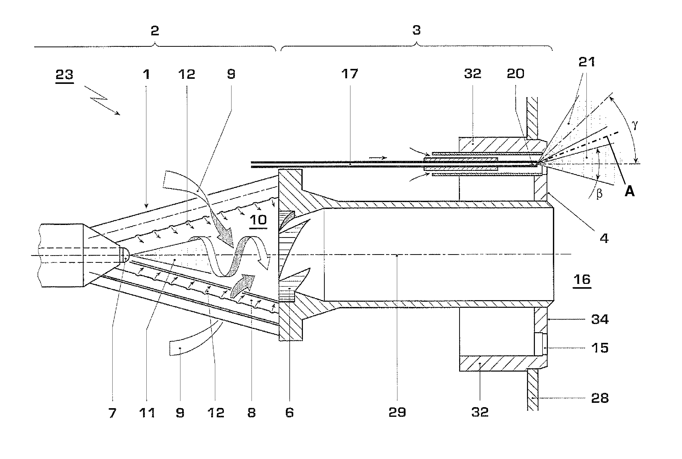
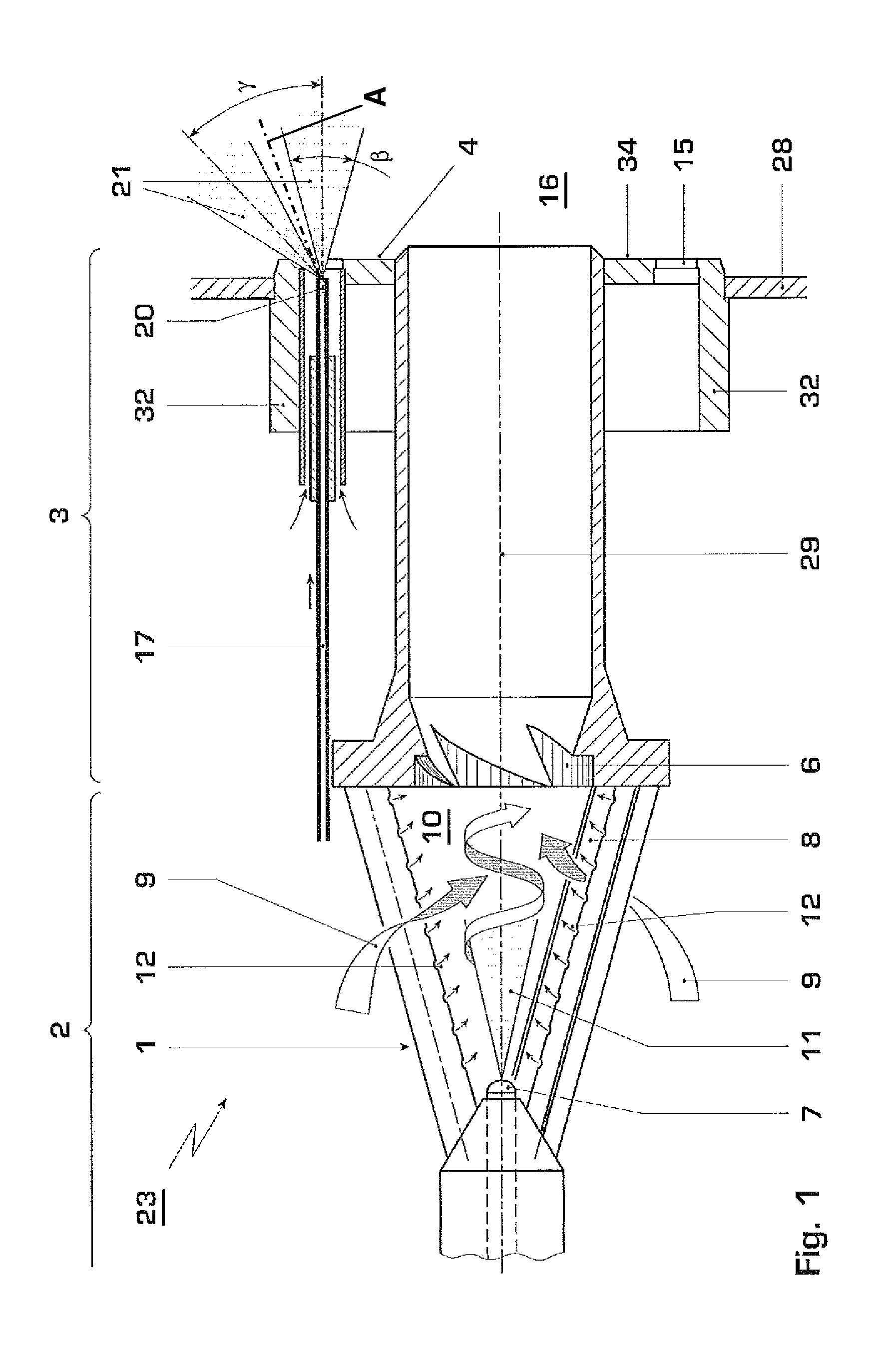
[0037]FIG. 1 schematically shows in a central section a burner of the type as is described for example in EP 0 704 657 B1 or in EP 0 780 629 B1. Such a burner 23 has a swirler 2 which is formed as a result of the offset arrangement of at least two conical body sections 1. As a result of this offset arrangement, tangential inlet slots 8 are formed between the two body sections 1. The combustion air 9 enters the burner cavity 10 through these tangential inlet slots 8, wherein a high swirl is generated. A fuel nozzle 7 for liquid fuels is arranged at the central apex of the cone.

[0038]The fuel which discharges from this fuel nozzle 7 forms a fuel cone 11 and is picked up by the tangentially inflowing combustion air 9 and enveloped by this, and a conical column consisting of a mixture of fuel and combustion air is formed. Gaseous fuel can be fed in the region of the tangential inlet slots 8 via additional fuel nozzles 12.

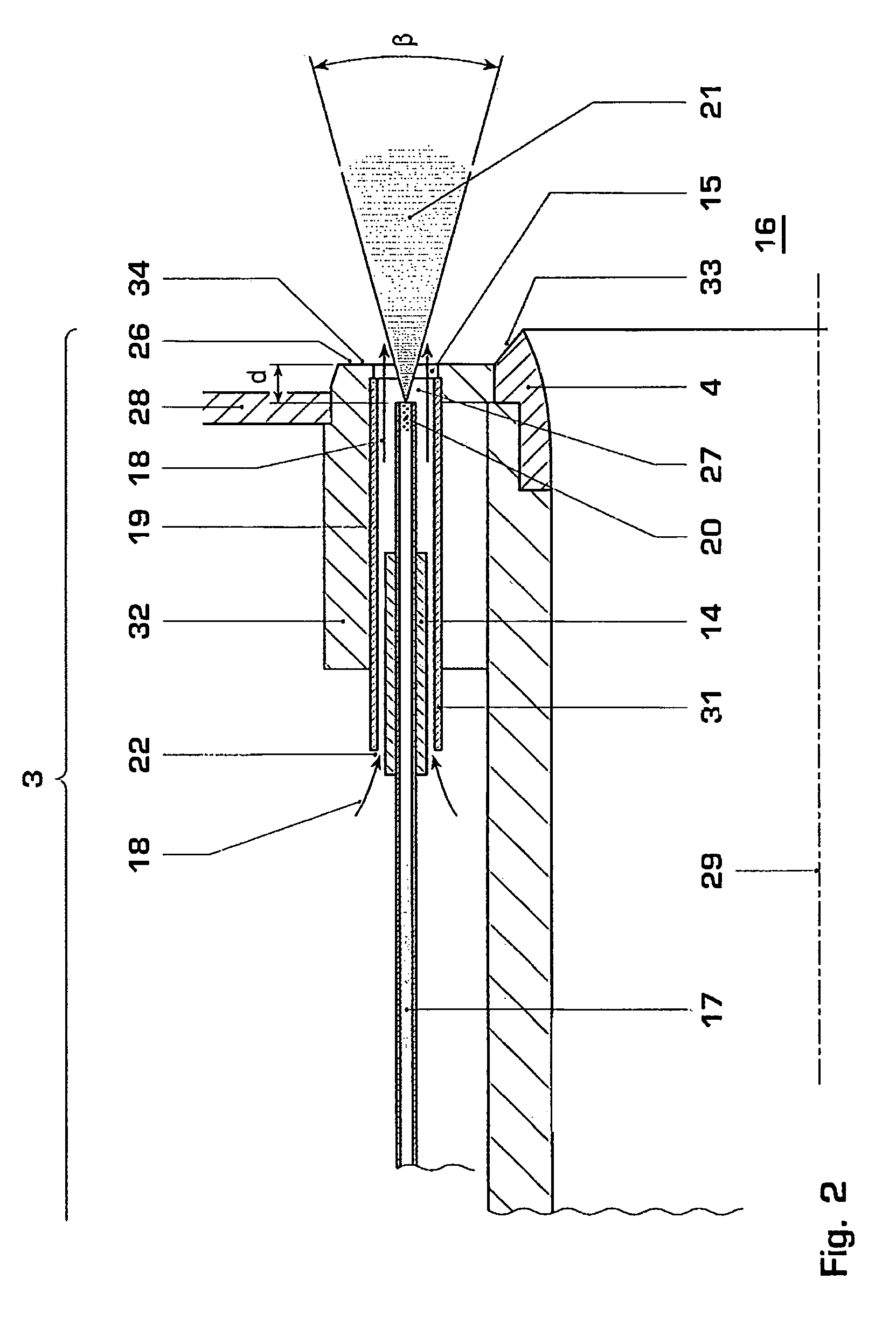
[0039]A mixing path 3 is connected downstream to this swirler 2. T...


PUM


Abstract

A burner (23) for operating a heat generator includes a swirler (2) for a combustion air flow (9), and also devices (7, 12) for injecting at least one fuel into the combustion air flow (9), wherein a mixing path (3) is arranged downstream of the swirler (2), and wherein at least one nozzle (20) for feeding liquid pilot fuel is arranged in the region radially outside the discharge opening of the mixing path (3) of the burner. With such a burner, an operating mode which is as pollutant-free and overheating-free as possible can be enabled even at low load and under transient conditions if the at least one nozzle (20) is arranged in a burner front plate (32), wherein at least one discharge opening (15), through which the pilot fuel discharges into the combustion chamber (16), is provided in a front face (34) of the burner front plate (32), which is arranged essentially parallel to a combustion chamber rear wall (28).

Description

[0001]This application is a Continuation of, and claims priority under 35 U.S.C. §120 to, International application no. PCT / EP2007 / 052031, filed 5 Mar. 2007, and claims priority therethrough under 35 U.S.C. §§119, 365 to Swiss application no. 0477 / 06, filed 27 Mar. 2006, the entireties of which are incorporated by reference herein.BACKGROUND[0002]1. Field of Endeavor[0003]The present invention relates to a burner for operating a heat generator, wherein such a burner has a swirler for a combustion air flow, and also means for injecting at least one fuel into the combustion air flow. Downstream of the swirler, a mixing path is arranged, and in the region radially outside the discharge opening of the mixing path of the burner there is at least one nozzle for feeding liquid pilot fuel. Furthermore, the present invention relates to a method for operating such a burner.[0004]2. Brief Description of the Related Art[0005]Premix burners, as proposed for example in EP 0 321 809 B1, are burner...

Claims


Application Information

Patent Timeline
Patent Type & Authority Patents(United States)
IPC IPC(8): F23Q9/00
CPCF23C7/008F23D17/002F23R3/343F23C2900/07002
Inventor BERNERO, STEFANOFLOHR, PETEROOMENS, GIJSBERTUSZAJADATZ, MARTIN
Owner GENERAL ELECTRIC TECH GMBH
Why Eureka
Try Eureka