Arrangement structure of radiator reservoir tank of motorcycle

a radiator and reservoir tank technology, applied in the direction of machines/engines, cycles, transportation and packaging, etc., can solve the problem of difficult disposal of reservoir tanks having a large volume, and achieve the effect of improving the mobility of the motorcycle, and easy supply of water

Inactive Publication Date: 2011-07-12
HONDA MOTOR CO LTD
View PDF45 Cites 7 Cited by
  • Summary
  • Abstract
  • Description
  • Claims
  • Application Information

AI Technical Summary

Benefits of technology

[0009]According to this configuration, since an intake port is open at the rear side of the cylinder extending upwardly from the crankcase and a throttle body is connected to the intake port, it is possible to appropriately dispose the reservoir tank of the radiator in the vicinity of the engine, by effectively using the space formed above the crankcase, behind the cylinder, and under the throttle body. Further, since the reservoir tank is disposed in the vicinity of the engine, heavy parts are disposed near to the center of gravity, that is, the mass is concentrated, such that it is possible to improve mobility of the motorcycle.
[0010]In the configuration, the throttle body may be configured to have a pulley and an operation wire for operating a throttle valve, disposed at one side, and a water supply port of the reservoir tank disposed at the other side of the throttle body. According to this configuration, since the water supply port of the reservoir tank is disposed on the opposite side to the pulley and the operation wire of the throttle body, the pulley and the operation wire do not interfere with the water supply port and it is possible to easily supply water to the reservoir tank through the water supply port.
[0011]Further, a clutch may be disposed on a side of the crankcase, one side of the upper surface of the crankcase may be formed higher than the other side, and the reservoir tank may be disposed on the other side of the upper surface of the crankcase. According to this configuration, since the reservoir tank is disposed on the upper surface at the other side of the crankcase, which is lower than the one side, the height between the upper surface at the other side of the crankcase and the throttle body can be larger than that at one side of the crankcase and it is possible to dispose a reservoir tank having a large volume within the space formed above the crankcase, behind the cylinder, and under the throttle body.
[0012]According to an embodiment of the present invention, since the intake port is open at the rear side of the cylinder extending upwardly from the crankcase and the throttle body is connected to the intake port, it is possible to appropriately dispose the reservoir tank of the radiator in the vicinity of the engine, by effectively using a space formed above the crankcase, behind the cylinder, and under the throttle body. Further, since the reservoir tank is disposed in the vicinity of the engine, heavy parts are disposed near to the center of gravity, that is, the mass is concentrated, such that it is possible to improve the mobility of the motorcycle.
[0013]Further, since the water supply port of the reservoir tank is disposed at the opposite side to the pulley of the throttle body and the operation wire, the pulley and the operation wire do not interfere with the water supply port and it is possible to easily supply water to the reservoir tank through the water supply port.

Problems solved by technology

However, it is difficult to dispose the reservoir tank having a large volume in the vicinity of the engine because of limited space.

Method used


Image

  • Arrangement structure of radiator reservoir tank of motorcycle
  • Arrangement structure of radiator reservoir tank of motorcycle
  • Arrangement structure of radiator reservoir tank of motorcycle

Examples


Embodiment Construction

[0022]An embodiment of the invention will be described hereafter with reference to the accompanying drawings. The following description will be made on the basis of a direction from a main body. In detail, in the following embodiment, the terms up, down, front, rear, left, and right mean the up, down, front, rear, left, and right from the main body.

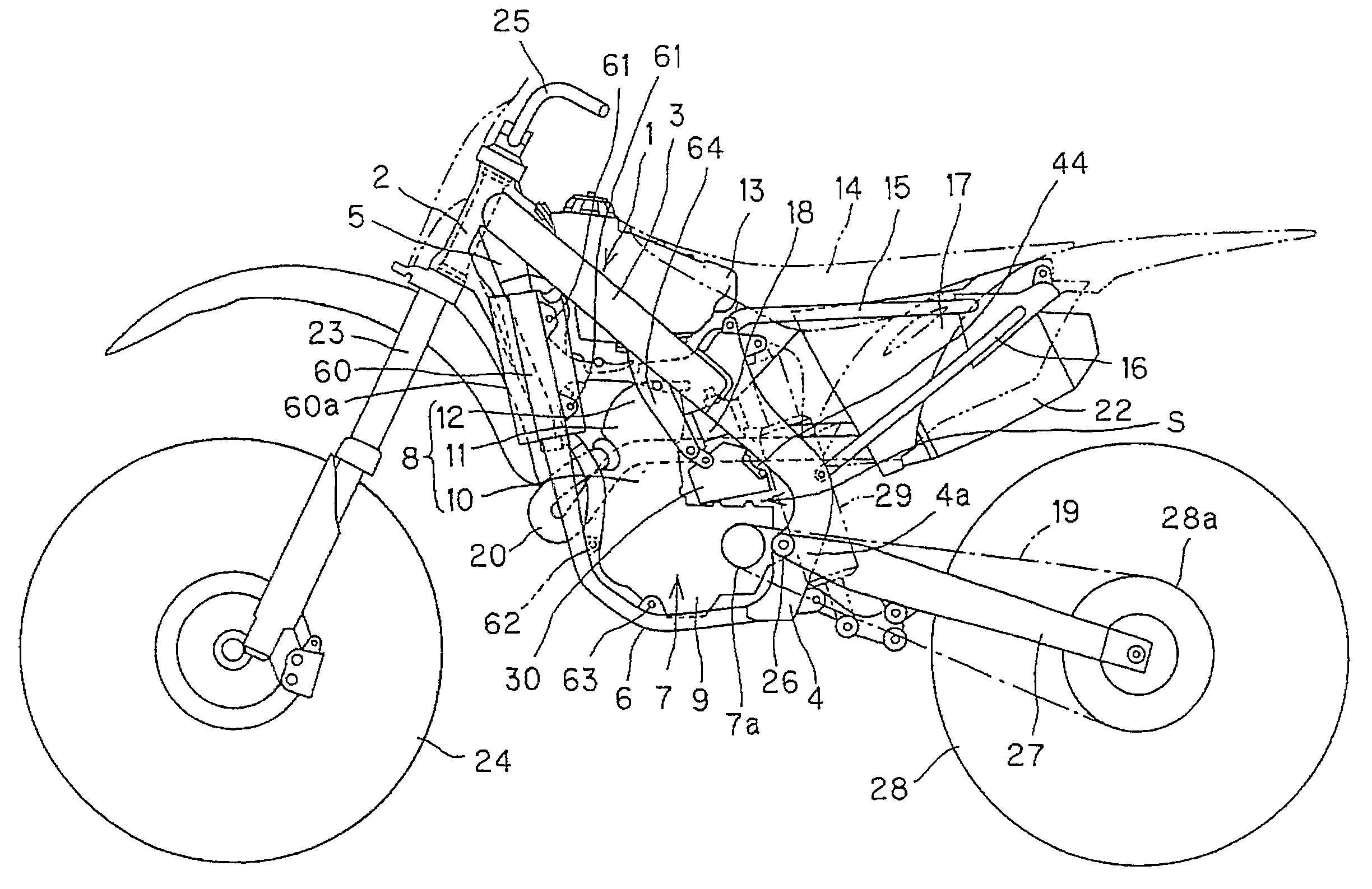
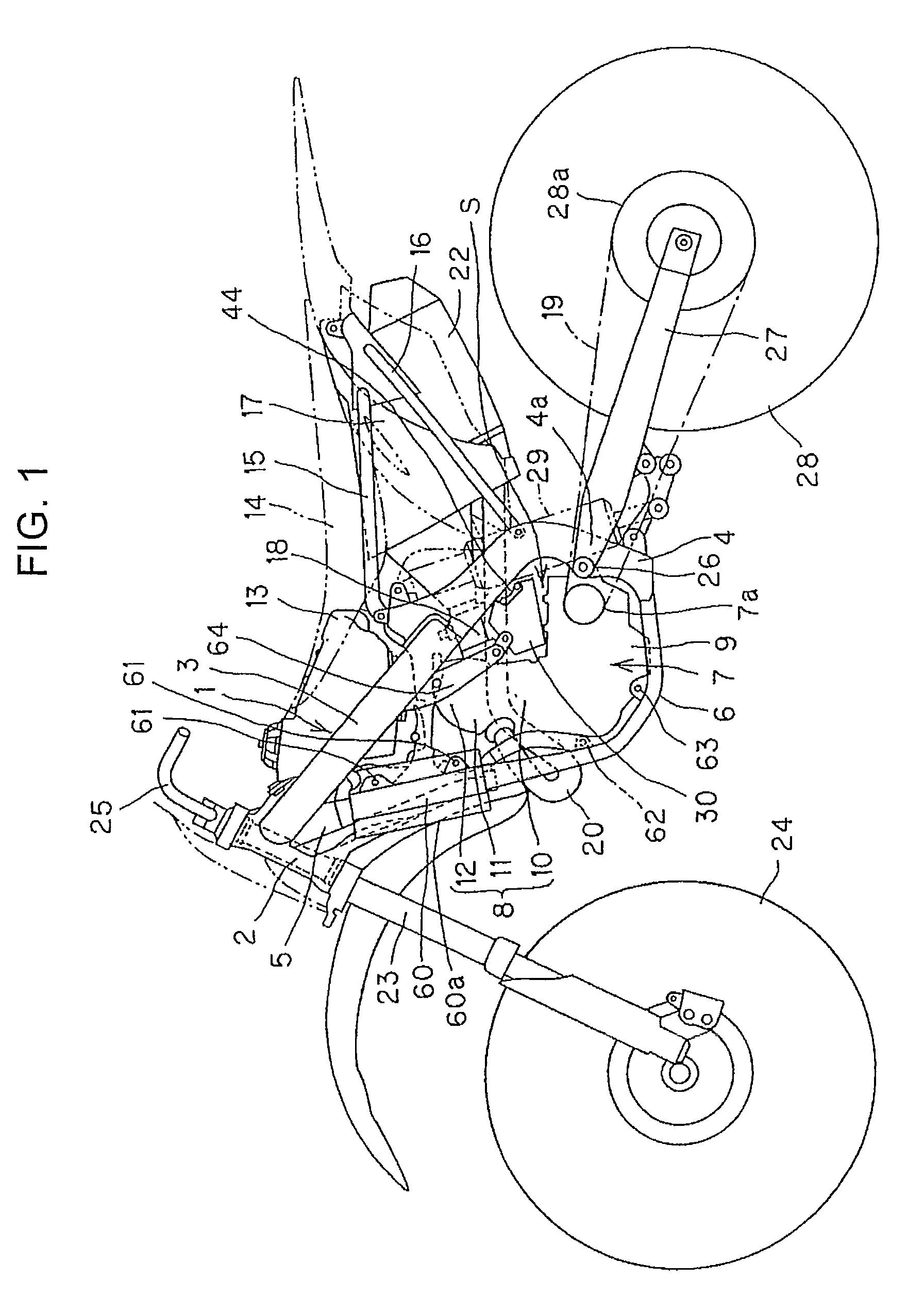
[0023]FIG. 1 is a side view of an off-road motorcycle according to this embodiment.

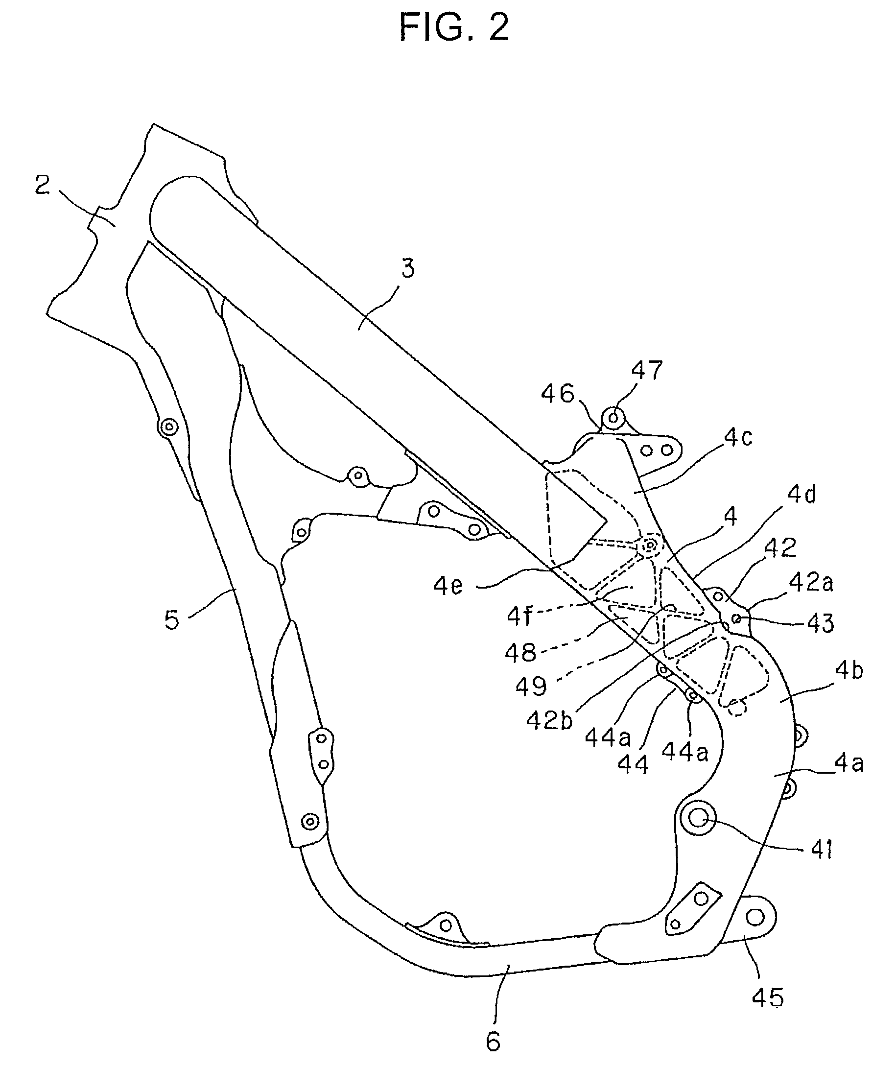
[0024]A main body frame 1 of the motorcycle includes a head pipe 2, a main frame (main tube) 3, a center frame 4, a down frame 5, and a lower frame 6, which are connected in a loop shape and an engine 7 is supported inside the loop. The engine 7 includes a crankcase 9 and a cylinder 8 extending upwardly from the front of the crankcase 9. The main frame 3, center frame 4, and lower frame 6 are each mounted in a pair at the left and right, and one head pipe 2 and one down frame 5 are mounted along the center line in the left-right direction of the main body.

[...


PUM


Abstract

An arrangement structure for a radiator reservoir tank for a motorcycle that makes it possible to appropriately dispose a reservoir tank of a radiator in the vicinity of an engine. A main frame is provided that extends to the rear side from a head pipe disposed at the front of a main body. An engine is disposed under the main frame, the engine includes a cylinder extending upward from a crankcase with an intake port open at the rear side of the cylinder. A throttle body is connected to the intake port with a reservoir tank of a radiator being disposed in a space S above the crankcase, behind the cylinder, and under the throttle body.

Description

CROSS-REFERENCE TO RELATED APPLICATIONS[0001]The present application claims priority under 35 USC 119 to Japanese Patent Application No. 2008-085325 filed on Mar. 28, 2008 the entire contents of which are hereby incorporated by reference.BACKGROUND OF THE INVENTION[0002]1. Field of the Invention[0003]The present invention relates to an arrangement structure of a radiator reservoir tank for a motorcycle equipped with a reservoir tank of a radiator in the vicinity of an engine.[0004]2. Description of Background Art[0005]In general, a motorcycle is known that is equipped with a water-cooled engine that includes a radiator for cooling water and a reservoir tank for storing an amount of an increase of the cooling water of the radiator according to an expansion due to an increase in the temperature of the radiator and supplies an amount of decrease of the cooling water due to a decrease in the temperature. See, for example JP Patent No. 2832827.[0006]According to the above configuration, ...

Claims


Application Information

Patent Timeline
Patent Type & Authority Patents(United States)
IPC IPC(8): B62M7/04
CPCB62K11/04F01P3/18F01P2050/16B60Y2200/12
Inventor ASANO, TATSUHIKO
Owner HONDA MOTOR CO LTD
Why Eureka
Try Eureka