Associating a universal time with received signal

a universal time and signal technology, applied in the field of associating a universal time with received signals, can solve the problems of not working well, not at all, inside buildings, and taking a long time to achieve a “first fix” and time aiding is therefore only available, so as to reduce the uncertainty of the time of arrival and reduce the range of time offsets

Active Publication Date: 2011-07-12
CAMBRIDGE POSITIONING SYST LTD
View PDF29 Cites 22 Cited by
  • Summary
  • Abstract
  • Description
  • Claims
  • Application Information

AI Technical Summary

Benefits of technology

[0041]The use of a repetitive identified component allows for averaging of several measurements of time of arrival information to produce a better estimate of a future, current, or past event. Having established the timing of the received signals in this way, the method of the invention may be used in an application for measuring perturbations in the incoming signals, for example in timing caused by transmission or path variations, or as an integrity check.

Problems solved by technology

Satellite positioning systems work well in situations where the receiver's antenna has clear sight of the sky, but they work poorly, or not at all, inside buildings or when the view of the sky is obscured.
Another problem is that they take a long time to achieve a “first fix” from a cold start and they therefore work best when they are tracking the satellite signals continuously.
In such cases, time aiding is therefore only available when the mobile terminal has access to a properly equipped terrestrial radio network.
Furthermore a significant amount of signalling and messaging is required both within the network, and between the network and the mobile terminal.
This is not straightforward for several reasons.
Second, there is always a processing delay between the reception of a signature in the network signal and the detection of the signal by the base-band processor in the terminal.
This delay may be measured in milliseconds, and is therefore substantial when fine time aiding at the level of a few microseconds is needed.
Third, as the position of the mobile terminal changes, the time information has a transmission delay (time of flight component) which depends upon the relative location of the mobile terminal and the transmission source.
Whilst straightforward to implement, this invention fails to deal with the processing delay in the generation of the trigger pulse, so cannot be used for the provision of fine time aiding with microsecond accuracy.
Nor does Syrjarinne deal with the problem of correcting the timing of the trigger pulse to compensate for motion of the communications or user module.

Method used


Image

  • Associating a universal time with received signal
  • Associating a universal time with received signal
  • Associating a universal time with received signal

Examples


Embodiment Construction

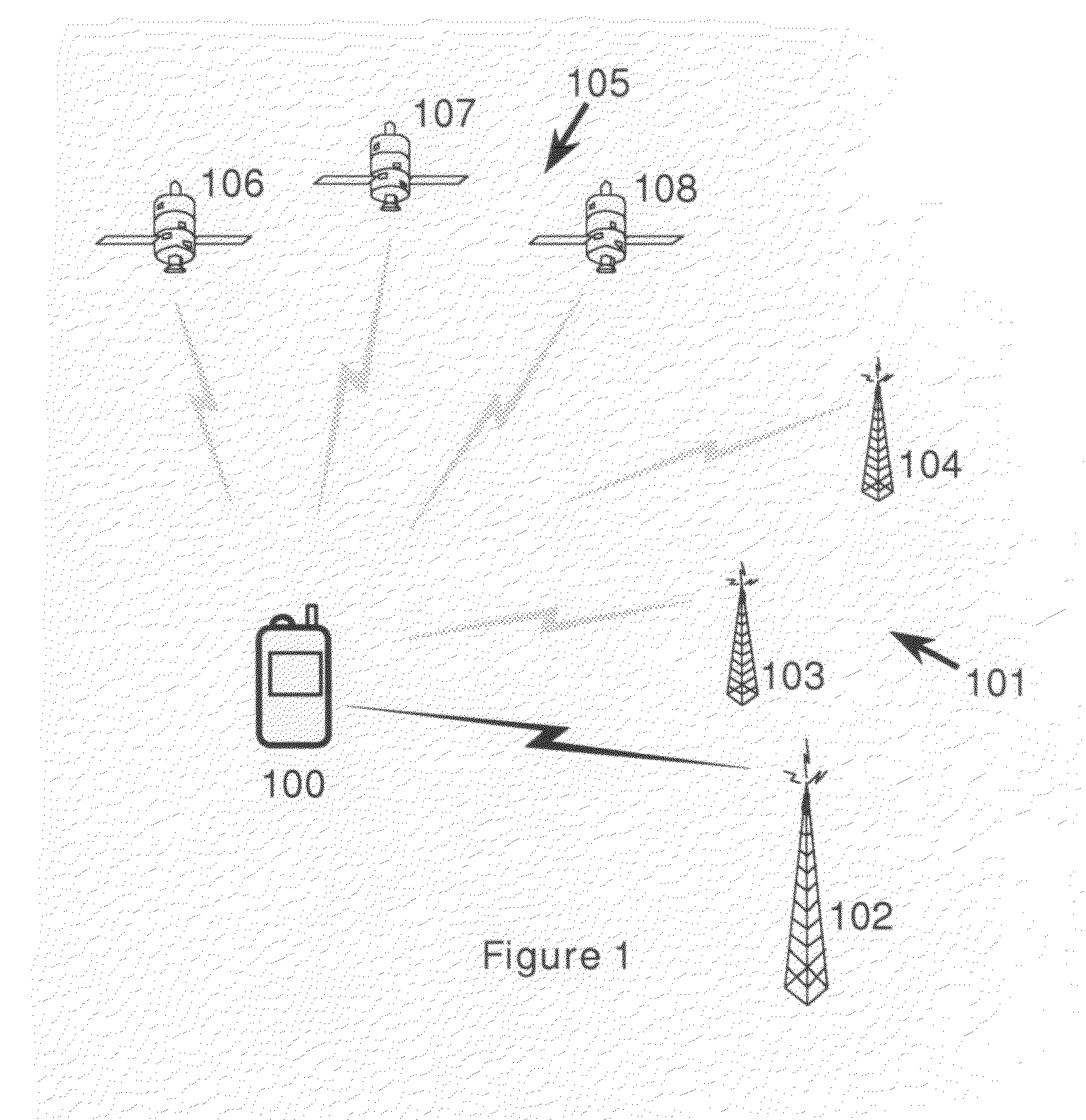
[0071]FIG. 1 shows a terminal 100 of a GSM communications network 101 with associated serving base transceiver station 102 and neighbouring base transceiver stations 103 and 104. The terminal 100 has a communications module including a receiver 201 for receiving the transmissions from the network 101, but it also has a receiver 208 for receiving GPS signals from a satellite positioning system 105, specifically from the satellites 106, 107,108 etc.

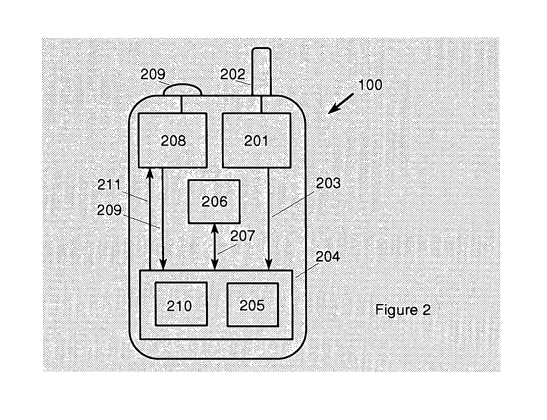
[0072]The terminal 100 is shown in more detail in FIG. 2. The receiver 201 of the communications module receives the signals from communications network 101 via an antenna 202, and transfers base-band I and Q samples (i.e. in-phase and quadrature-phase) via link 203 to a processor 204. The processor is running a software program 205 which is able to recognise the arrival of an identified component in the signal, in this case the ETS. The processor 204 receives clock signals, count data, and pulses from counter 206 via a bi-directional link ...


PUM


Abstract

A method of associating a universal time with time of arrival information of an identified component of a signal at a terminal of a radio positioning system is disclosed. In the method a marker signal with an associated universal time tag is obtained from a timing device (or the marker signal is obtained from an independent oscillator and a universal time tag assigned to the marker signal), and the time or phase relationship between the marker signal (or between the time of arrival information of said identified component respectively) and the oscillator is measured. The time of arrival information of said identified component relative to the oscillator is determined and the universal time corresponding to the time of arrival information of said identified component is calculated from said universal time tag and said measured time or phase relationship, before the calculated universal time is associated with said time of arrival information.

Description

FIELD OF THE INVENTION[0001]The invention relates generally to systems for finding the position of a terminal of a communications or other network, and more particularly to the provision of time assistance to an associated device such as a receiver of a satellite positioning system (such as GPS or Galileo). Specifically, the invention provides a method of associating a universal time with time of arrival information of an identified component of a signal at a terminal of a radio positioning system.BACKGROUND AND PRIOR ART[0002]Technology for positioning mobile radio terminals using the signals received from one or more transmitters has been widely used for many years. Such systems include terrestrial networks of transmitters (e.g. Loran) and networks of satellites (e.g. GPS and Galileo) deployed specifically for the purpose of locating the receiver, as well as methods that use general-purpose radio networks such as cellular mobile telephone networks (e.g. WO-A-97-11384) or TV and ra...

Claims


Application Information

Patent Timeline
Patent Type & Authority Patents(United States)
IPC IPC(8): G01S1/24H01Q3/00G01S19/23
CPCG01S19/23
Inventor DUFFETT-SMITH, PETER JAMESHANSEN, PAULPRATT, ANTHONY RICHARD
Owner CAMBRIDGE POSITIONING SYST LTD
Why Eureka
Try Eureka