Card dispensing apparatus
a card and card surface technology, applied in the field of smallcard dispensing apparatuses, can solve the problems of large contact pressure between the roller and the card surface, damage, and roller rubbing, and achieve the effects of reducing the contact pressure, low cost, and downsizing and configuration
- Summary
- Abstract
- Description
- Claims
- Application Information
AI Technical Summary
Benefits of technology
Problems solved by technology
Method used
Image

Examples
first embodiment
[0234]First, concerns in the card dispensing apparatus in the first embodiment are described with reference to FIG. 23.
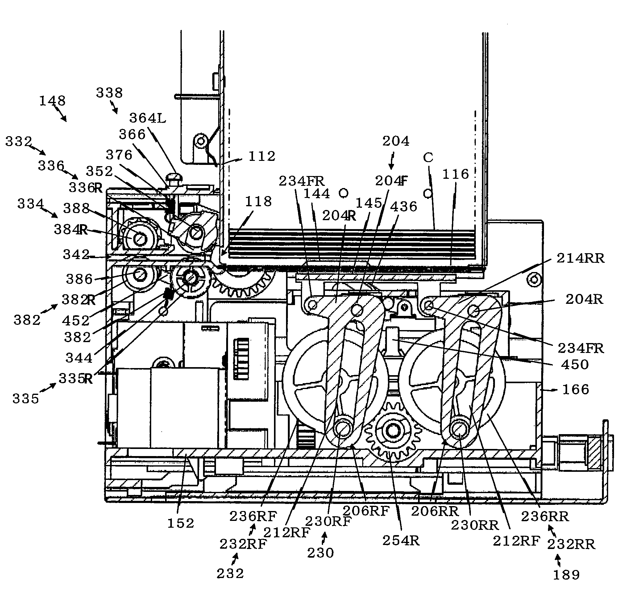
[0235]In this card dispensing apparatus, at the time of initial setting, the card C at the bottom is positioned inside the holding room 114 (refer to FIG. 23 (A)). When the card C at the bottom is dispensed to a drawing unit 148 side with a dispensing movement of the dispensing unit 104, the card C at the bottom passes through a gap between the roller 335 and the reverse-rotation roller 336 to advance to a feeding unit 334 side. A card C2 thereon is drawn together with a frictional contact, but is prevented from advancing by the reverse-rotation roller 336 constituting a two-sheet dispensing preventing unit 332, and therefore is not moved to a feeding unit 334 side (refer to FIG. 23 (B)).
[0236]Also, a card C3, which is mounted on the card C2 and which could potentially pass through the exit opening 122, is prevented from advancing by the reverse-rotation roller 336,...
second embodiment
[0240]The second embodiment can prevent such an over-dispensing.
[0241]The second embodiment is described with reference to FIG. 21, where portions identical to those in the first embodiment are provided with the same reference numerals, and only the different portion is described. An inclined surface for pushing 462 is formed at a rear end of the base 116 of the holding member 106 constituting the card holding unit 102. The inclined surface for pushing 462 is inclined downward toward the front at an angle of approximately 45 degrees.
[0242]In other words, the inclined surface for pushing 462 is inclined downward toward the front to the drawing unit 148, and its lower end approaches the exit 122 by approximately five millimeters. With this configuration, several lower ones of the cards C stacked inside the holding room 114 have their rear ends (end portions on a side opposing to the exit 122) make contact with the inclined surface for pushing 462. Then, with the weight of the cards C ...
third embodiment
[0250]the present invention is an embodiment where, since the card is drawn by the feeing unit at a higher speed than the card dispensing unit, even when the amount of stacking cards is increased, difficulty in drawing by the feeding unit can be prevented, as a result, allowing an increase in the amount of stacking cards.
[0251]Specifically, in the card dispensing apparatus according to the first and second embodiments, in the state where the dispensed card is fed by the feeding unit, the conveying member makes contact with the lower surface of the card at the bottom for a predetermined time and the card at the bottom will have approximately the entire weight of the stacked cards applied.
[0252]The conveying member is formed of a material with a high coefficient of friction so as not to cause any sliding with the card as much as possible. With this, when the amount of stacking cards is increased, the contact pressure between the conveying member and the lower surface of the card is in...
PUM
 Abstract
Description
Claims
Application Information
 - R&D
- Intellectual Property
- Life Sciences
- Materials
- Tech Scout
- Unparalleled Data Quality
- Higher Quality Content
- 60% Fewer Hallucinations
Browse by: Latest US Patents, China's latest patents, Technical Efficacy Thesaurus, Application Domain, Technology Topic, Popular Technical Reports.
© 2025 PatSnap. All rights reserved.Legal|Privacy policy|Modern Slavery Act Transparency Statement|Sitemap|About US| Contact US: help@patsnap.com