Micro position-control system

a position control system and micro-chip technology, applied in the field of micro-position control systems, can solve the problems of high drawbacks of general position control systems, limit the precision of the position that can be achieved, and the difficulty of performing a vertical position control in works that require high precision, so as to achieve greater precision

Inactive Publication Date: 2007-05-15
SAMSUNG ELECTRONICS CO LTD
View PDF8 Cites 13 Cited by
  • Summary
  • Abstract
  • Description
  • Claims
  • Application Information

AI Technical Summary

Benefits of technology

[0018]The present invention provides a position-control system that can move in a wide range by keeping the overall height of a motion stage within a predetermined range (e.g., 25 mm) using an elastic hinge mechanism having a bridge structure and also by mechanically amplifying an amount of deformation of a piezo actuator. The present invention also provides a position-control system that can control the degrees-of-freedom of a Z-direction translation motion and X-axis and Y-axis rotations with greater precision.

Problems solved by technology

General position-control systems using a linear motor or both a servo motor and a ball screw have a relatively long stroke distance but have a limit to the position precision that can be achieved due to a structural limit, such as a backlash or the like.
Also, general position-control systems have a drawback of becoming high due to vertically arranging actuators for the purpose of obtaining vertical motion.
This drawback causes much difficulty in performing a vertical position control in works that require high precision.
Also, actuators used in the micro-precise position-control systems must be easily driven through a distance of micrometers or less and must be highly repetitive.
In the related patent, first, a thin circular hinge portion is prone to be deformed in all directions as well as being bent.
Hence, the rigidity and stability of the entire system are very poor.
Hence, a precise operation of the position-control system is difficult.
Thus, control is difficult.
Third, since the thin hinge portion receives a large force directly from piezo actuators, the thin hinge portion is very likely to be broken or plastically deformed even by a small external force.
However, the manufacture of a plane motion stage having degrees-of-freedom including a Z-direction translation motion, an X-axis rotation, and a Y-axis rotation is not easy because wire electro-discharge machining, which is generally used to manufacture an elastic hinge, cannot achieve three-dimensional machining, it can only achieve two-dimensional machining.
In addition, although a stacked piezo actuator, which is frequently used as a driving source of a micro driving mechanism, has great driving power and excellent resolving power of several nanometers or less, the stacked piezo actuator has a drawback in that its deformation range is limited to about 0.1% of the overall length of the actuator.

Method used


Image

  • Micro position-control system
  • Micro position-control system
  • Micro position-control system

Examples


Embodiment Construction

[0044]The present invention will now be described more fully with reference to the accompanying drawings, in which exemplary embodiments of this invention are shown. Advantages and features of the present invention and methods of accomplishing the same may be understood more readily by reference to the following detailed description of exemplary embodiments and the accompanying drawings. The present invention may, however, be embodied in many different forms and should not be construed as being limited to the exemplary embodiments set forth herein. Rather, these exemplary embodiments are provided so that this disclosure will be thorough and complete and will fully convey the concept of the invention to those skilled in the art, and the present invention will only be defined by the appended claims. Like reference numerals refer to like elements throughout the specification.

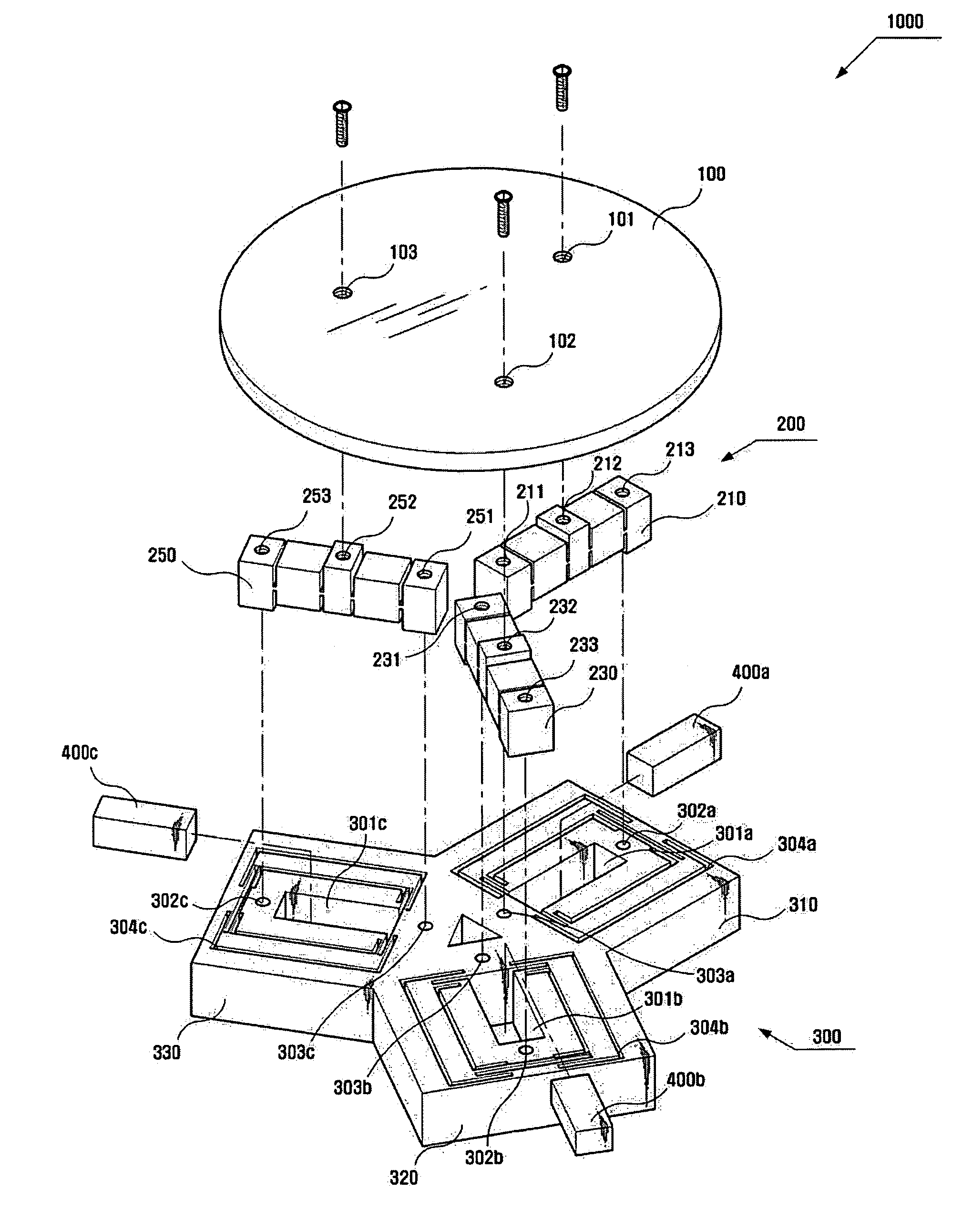
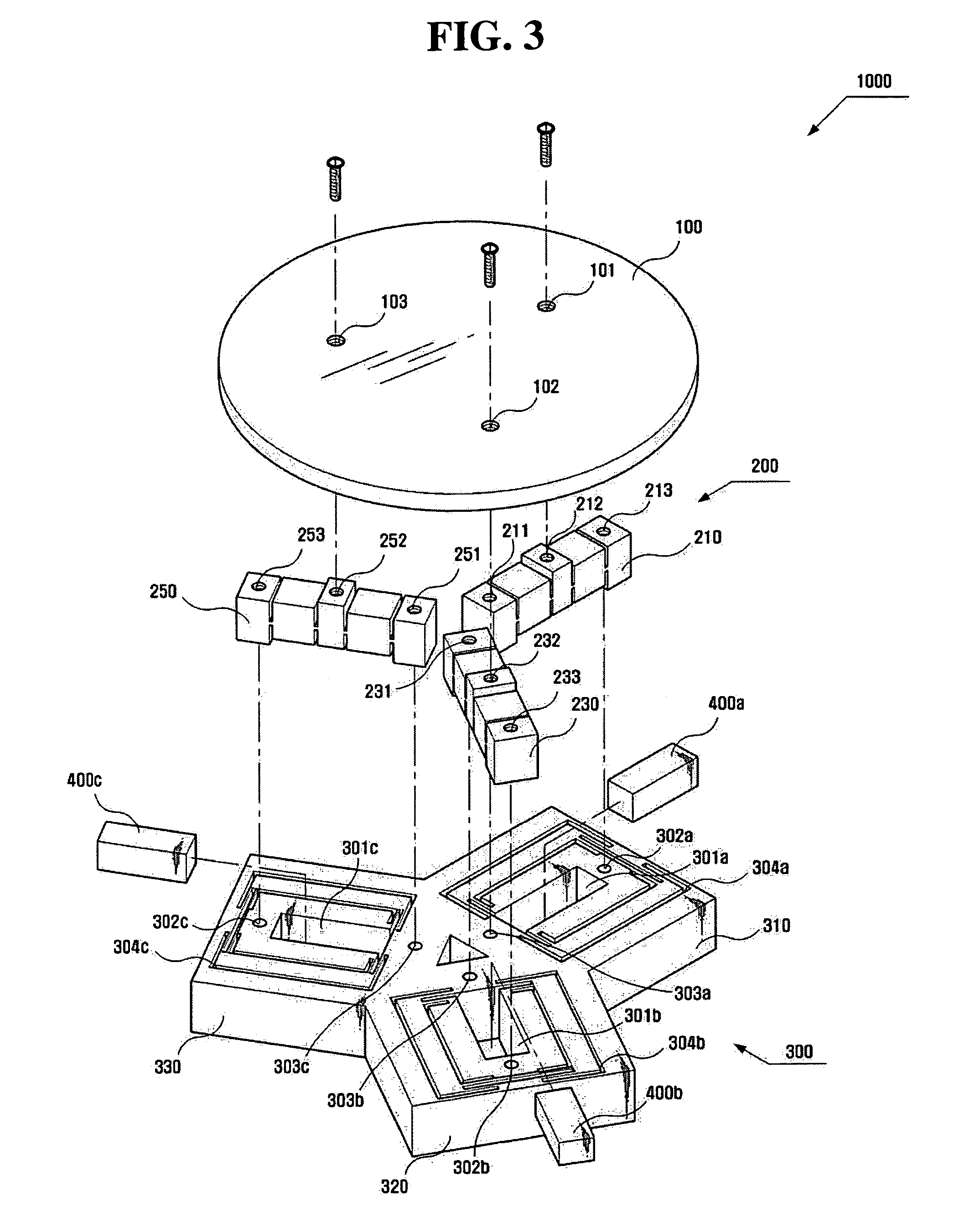
[0045]FIG. 3 is an exploded perspective view of a micro position-control system 1000 according to an exemplary e...


PUM


Abstract

A micro position-control system capable of more precisely controlling three degree-of-freedom motions, namely, a Z-direction motion and X-axis and Y-axis rotations. The micro position-control system includes a base including a plurality of base units disposed at equal angles from the center of a motion stage, holding piezo actuators parallel to a direction of the disposition of the base units, a plurality of bridge units disposed to face the base units, converting a displacement in a length direction of the piezo actuators into a displacement that is vertical with respect to a bottom surface of the base, the motion stage making at least one of a translation motion in the vertical direction, a rotation about a first axis perpendicular to the vertical direction, and a rotation about a second axis perpendicular to both the vertical direction and the first axis, and a control unit controlling the piezo actuators.

Description

CROSS-REFERENCE TO RELATED APPLICATION[0001]This application claims priority from Korean Patent Application No. 10-2004-0062092 filed on Aug. 6, 2004 in the Korean Intellectual Property Office, the disclosure of which is incorporated herein by reference in its entirety.BACKGROUND OF THE INVENTION[0002]1. Field of the Invention[0003]The present invention relates to micro position-control systems and, more particularly, to a micro position-control system capable of more precisely controlling three degree-of-freedom motions, namely, a Z-direction motion, an X-axis rotation, and a Y-axis rotation.[0004]2. Description of the Related Art[0005]As is well known, the importance of micro position systems in industry increases day by day. Particularly, the development of semiconductor technology requires a high integration of a circuit, and consequently, a line width used in up-to date microprocessor circuits is about 0.18 μm. In this case, a motion stage for manufacturing a wafer requires pre...

Claims


Application Information

Patent Timeline
Patent Type & Authority Patents(United States)
IPC IPC(8): H01L41/09H02N2/04
CPCH02N2/0095H02N2/043B23Q15/22B23Q1/34B23Q5/28H02N2/001B23Q16/008
Inventor KIM, JUN-HYUNG
Owner SAMSUNG ELECTRONICS CO LTD
Why Eureka
Try Eureka