Earthing equipment for switchgear

a switchgear and equipment technology, applied in the direction of switchgear with a retractable carriage, non-enclosed substations, substations, etc., can solve the problems of difficult earthing, difficult earthing, and difficult earthing, and achieve the effect of easy earthing

Inactive Publication Date: 2011-07-19
HITACHI LTD
View PDF10 Cites 3 Cited by
  • Summary
  • Abstract
  • Description
  • Claims
  • Application Information

AI Technical Summary

Benefits of technology

[0010]The present invention is carried out in view of the above matters and an object of the present invention is to provide earthing equipment for a switchgear which permits an earthing connection easily even in an instance where height of a connecting portion of a main circuit at a panel side is modified due to difference of earthing portion.

Problems solved by technology

In earthing equipment for a switchgear using bare conductors for a main circuit, because the conductors in the main circuit are bare conductors, there is an advantage that an earthing work during a maintenance and inspection work can be performed from any arbitrary portion of the conductors, however, the energized portion thereof is exposed in a bare state, there is a danger of electrical shock depending on circumstances.
Namely, under a completely no voltage condition in an electric power installation, namely, in an instance of complete shutdown, there is no danger of electrical shock, however, when a maintenance and inspection work is performed while shutting down the load side under an active condition of bus bars in a main circuit (under a partial shutdown), the work has to be performed at portions near an active line, which is very dangerous.
However, even in such switchgear using insulated bus bars, it is dangerous to perform an earthing work while a worker getting into inside the panel, and the work efficiency is not desirable.
However, due to differences of earthing portions (stages of switchgear) where the main circuit of the switchgear is earthed, there sometimes happens that a position of a connecting portion to a bus bar of the main circuit does not match to a position of an earthing terminal of the carrying cart for earthing.
In such instance, a plurality of carrying carts for earthing have to be manufactured in which a contact for earthing that matches to a connecting portion to a bus bar of the main circuit and a manipulating mechanism for earthing are respectively different, therefore, the cost of building such installation becomes expensive.
Further, because the structures of the respective carrying carts are different, when apparatus on the carrying carts for earthing malfunctions, since the common use and arrangement of the constitutional parts are disturbed, a new production of parts is also necessitated, and in addition a problem also arises that a significant amount of time and expense for the exchanging work is incurred.

Method used


Image

  • Earthing equipment for switchgear
  • Earthing equipment for switchgear
  • Earthing equipment for switchgear

Examples


Embodiment Construction

[0020]Herein below, an embodiment of earthing equipment for a switchgear according to the present invention will be explained with reference to the drawings.

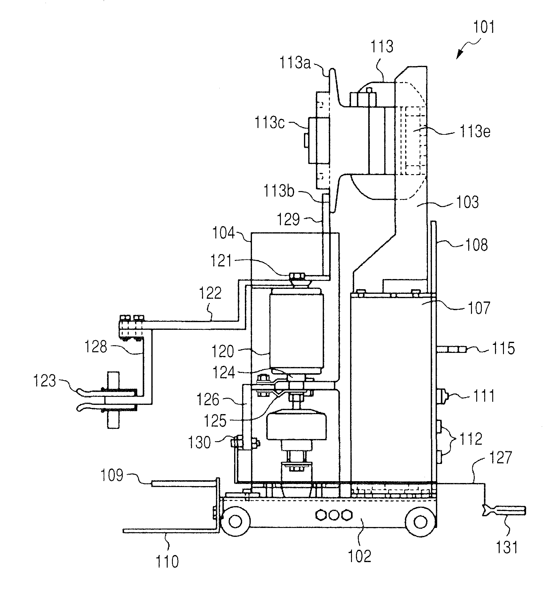
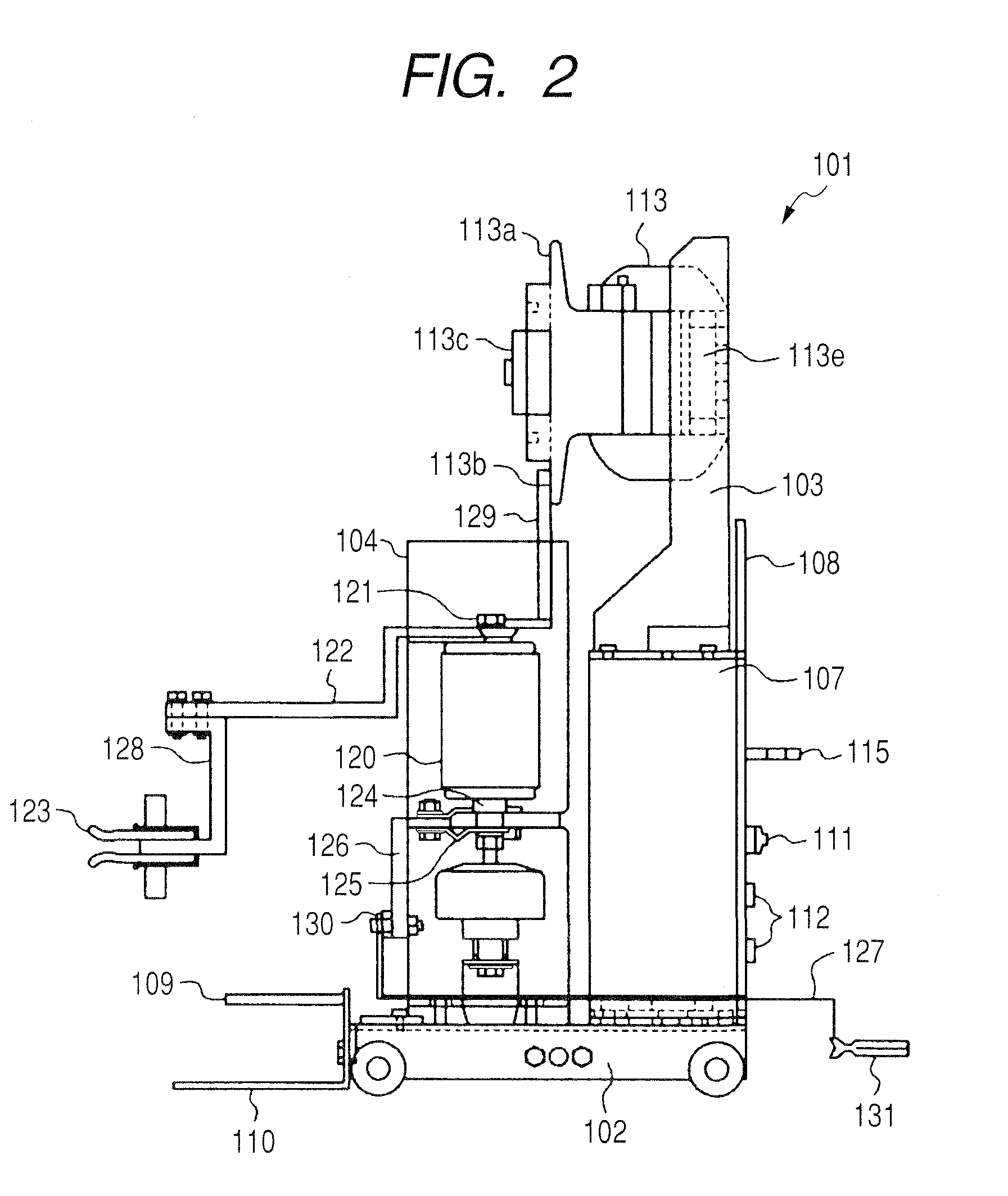
[0021]FIG. 1 through FIG. 4 show the embodiment related to the earthing equipment for the switchgear according to the present invention, wherein FIG. 1 is a partially cross sectioned side view of a solid insulated bus bar type switchgear to which the embodiment of the earthing equipment is applied, FIG. 2 is a partially cross sectioned side view of the embodiment of the earthing equipment, FIG. 3 is a perspective view of the embodiment of the earthing equipment seen from the rear side thereof, and FIG. 4 is a perspective view of the embodiment of the earthing equipment seen from the front side thereof.

[0022]At first, the solid insulated bus bar type switchgear to which the embodiment of the earthing equipment is applied will be explained. In FIG. 1, a housing 1 for the solid insulated bus bar type switchgear is partitioned into ...


PUM


Abstract

Earthing equipment for a switchgear is comprised of a movable carrying cart, a switch portion, a manipulating portion, and a voltage detecting device. The earthing equipment is provided with: an upper conductor connected to any one of the movable electrode and the stationary electrode; a lower conductor connected to the other of the movable electrode and the stationary electrode, an earthing wire connecting the lower conductor to a terminal used for earthing of the switchgear; and an adaptor conductor being selectively connected to either a disconnection portion at a bus bar side or a disconnection portion at a cable side of the switchgear and is permitted to be selectively replaced on either upper or lower face of the upper conductor.

Description

CLAIM OF PRIORITY[0001]The present application claims priority from Japanese application serial no. 2009-36872, filed on Feb. 19, 2009, the content of which is hereby incorporated by reference into this application.FIELD OF THE INVENTION[0002]The present invention relates to earthing equipment for a switchgear, and more specifically, relates to the earthing equipment for a switchgear of multi stage stacking type.BACKGROUND OF THE INVENTION[0003]In earthing equipment for a switchgear using bare conductors for a main circuit, because the conductors in the main circuit are bare conductors, there is an advantage that an earthing work during a maintenance and inspection work can be performed from any arbitrary portion of the conductors, however, the energized portion thereof is exposed in a bare state, there is a danger of electrical shock depending on circumstances.[0004]Namely, under a completely no voltage condition in an electric power installation, namely, in an instance of complete...

Claims


Application Information

Patent Timeline
Patent Type & Authority Patents(United States)
IPC IPC(8): H02B11/00
CPCH02B13/0354H02B13/075H02B11/28H02B3/00
Inventor SHODA, KENICHIKUROGI, TAKUYATSUCHIYA, KENJIISHIKAWA, TAKUMINAKATSUGAWA, NAOKI
Owner HITACHI LTD
Why Eureka
Try Eureka