Shift register and liquid crystal display using same

a technology of shift register and liquid crystal display, which is applied in the field of shift register, can solve the problems of unstable shift register, impaired display quality of lcd devices using shift register, and conflict of signal outputting, and achieve the effect of stable output signal

Active Publication Date: 2011-07-19
INNOLUX CORP +1
View PDF9 Cites 20 Cited by
  • Summary
  • Abstract
  • Description
  • Claims
  • Application Information

AI Technical Summary

Benefits of technology

[0014]In one preferred embodiment, a shift register for providing a plurality of low level shift register signals, the shift register includes a plurality of shift register units connecting in series, each shift register unit comprising a first inversion circuit, a second inversion circuit, and a third inversion circuit. The third inversion circuit for receiving a first clock signal from an external circuit, which has a first transistor for outputting the first clock signal, and a second transistor for outputting a turning off signal. The first inversion circuit for receiving output signal from a pre-stage shift register unit and a second clock signal which is inversed to the first clock signal, and output a control signal to the third inversion circuit, which includes a third transistor in an on state, discharging at an output end for keeping a stable output signal. The second inversion circuit receives the output signal from the first inversion circuit, and outputting a control signal to control the turn-of of turn-off of the second transistor. The first clock signal is output through the first transistor and the second transistor is switched off under the control of the second inversion circuit, when the first inversion circuit inputs a turn-on signal to switch on the first transistor; in verse, the first transistor is switched off and the second transistor is switched on under the control of the second inversion circuit.

Problems solved by technology

Thus, the adjacent shift register units may cause a conflict of signal outputting due to the overlapping of the adjacent shift register signals.
Therefore, the shift register is unstable.
Accordingly, an LCD device using the shift register has impaired display quality because adjacent columns or rows may be scanned simultaneously.

Method used


Image

  • Shift register and liquid crystal display using same
  • Shift register and liquid crystal display using same
  • Shift register and liquid crystal display using same

Examples


Embodiment Construction

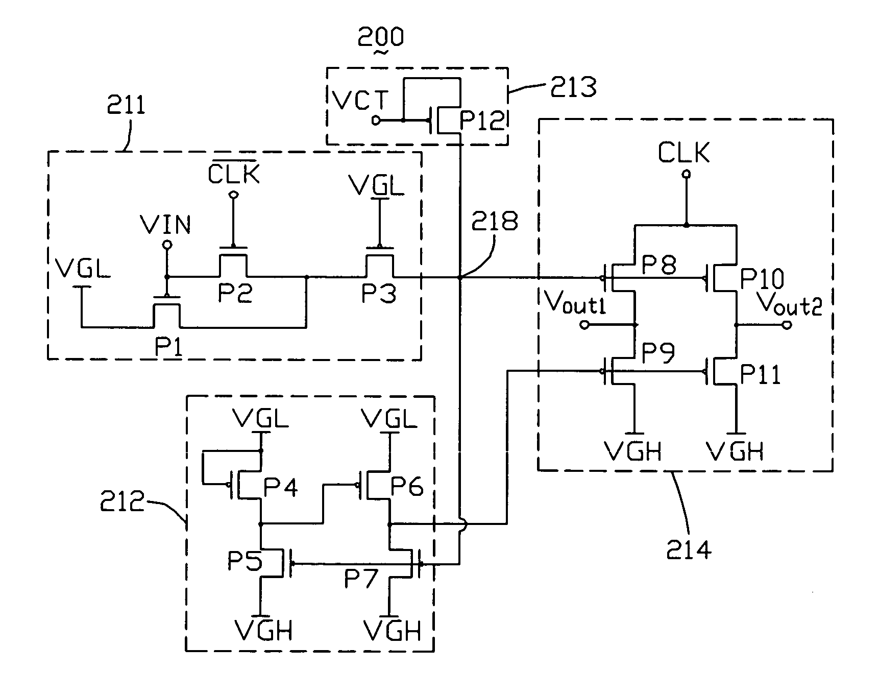
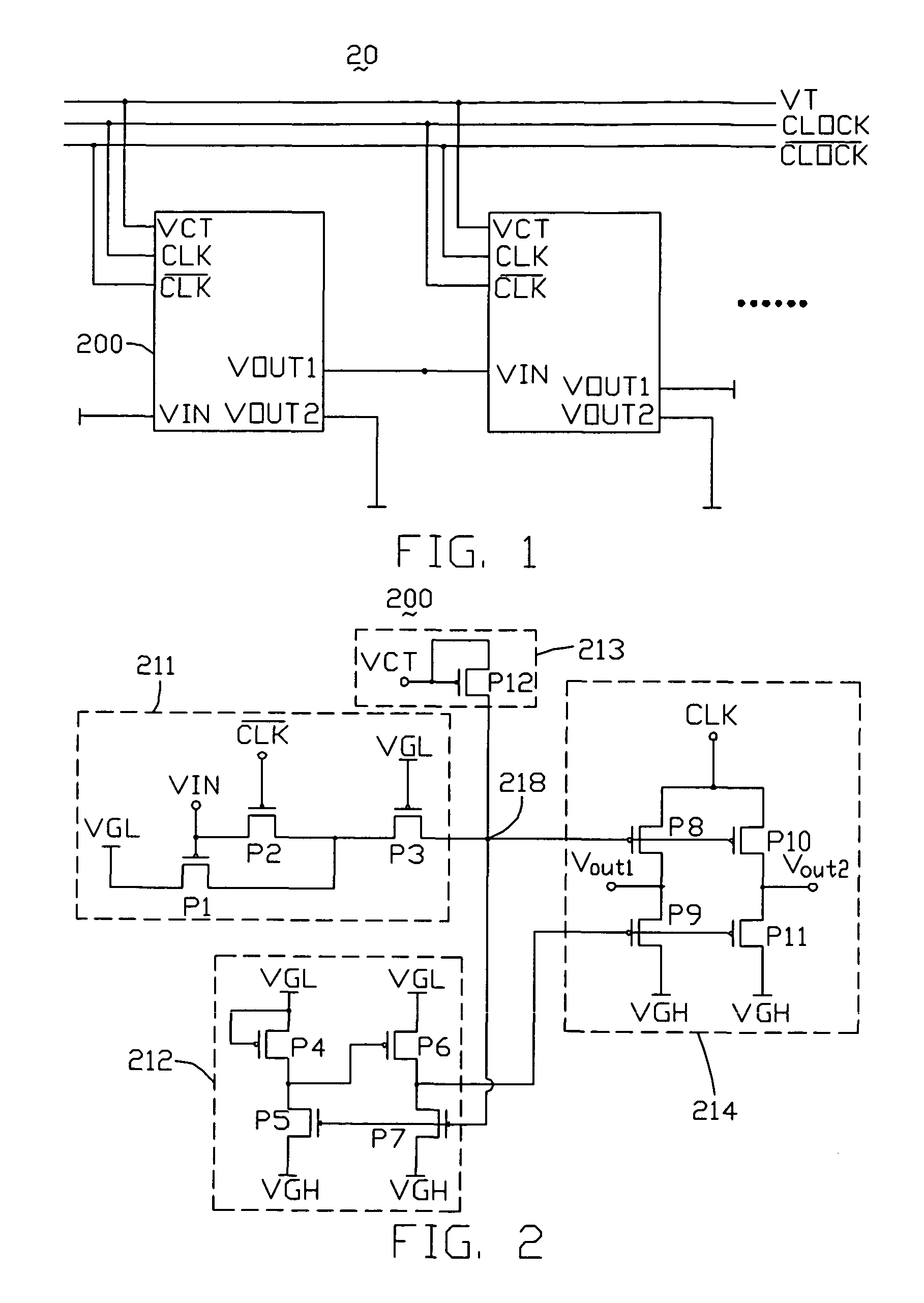
[0022]Referring to FIG. 1, a block circuit diagram of a shift register 20 according to an exemplary embodiment of the present invention is shown. The shift register 20 includes a plurality of shift register units 200 connected in series. The shift register units 200 have the same circuit structure. The shift register units 200 each include a clock signal input CLK, an inverse clock signal input CLK, a signal input VIN, a first output VOUT1, a second output VOUT2 and a test signal input VCT. The clock signal input CLK of the pre-stage shift register 200 is connected to an external circuit to receive clock signals, and the inverse clock signal input CLK is connected to the external circuit to receive inversed clock signals, and the signal input VIN is used to receive input signals, and the first output VOUT1 is connected to the signal input VIN of a rear-stage shift register unit 200, and the second output VOUT2 is configured to output signals to an external circuit. The rear-stage 20...


PUM


Abstract

An exemplary shift register (20) includes a plurality of shift register units (200). The shift register units receive a clock signal and an inverse clock signal and output a plurality of shift register signals in sequence. The outputs waveforms of pre-stage shift register unit and the rear-stage shift register unit have no overlapping signals.

Description

CROSS-REFERENCE TO RELATED APPLICATION[0001]This application is related to, and claims the benefit of, a foreign priority application filed in China as Application No. 200810067935.6 on Jun. 20, 2008. The related application is incorporated herein by reference.FIELD OF THE INVENTION[0002]This invention relates to shift registers, and more particularly to a shift register typically used in a driving circuit of a liquid crystal display without overlapping shift register signals.GENERAL BACKGROUND[0003]Shift registers are core circuit units of integrated circuits that are used in thin film transistor liquid crystal displays (TFT-LCDs). A shift register provides sequential pulse signals to scanning lines of a TFT LCD, so as to control on or off states of TFTs connected to the scanning lines.[0004]Referring to FIG. 5, this is a circuit diagram of a shift register unit 100 of a typical shifter register. The shift register unit 100 includes a first clock inversion circuit 110, an inverter ...

Claims


Application Information

Patent Timeline
Patent Type & Authority Patents(United States)
IPC IPC(8): G11C19/00
CPCG09G3/3677G09G3/3688G11C19/28G09G2310/0286G09G2320/0209
Inventor IEONG, MAN-FAICHEN, SZ-HSIAO
Owner INNOLUX CORP
Why Eureka
Try Eureka