Image blur correction unit, lens barrel device, and camera apparatus

a technology of image blur and correction unit, which is applied in the field of image blur correction unit, lens barrel device, and camera apparatus, can solve the problems of increased cost, difficult to reduce the thickness of the lens barrel, and increase the frequency of capturing images blurred, and achieve low-profile units, devices and apparatus, and high-accuracy correction

Inactive Publication Date: 2011-07-19
SONY CORP
View PDF12 Cites 22 Cited by
  • Summary
  • Abstract
  • Description
  • Claims
  • Application Information

AI Technical Summary

Benefits of technology

[0012]The present invention has been made in consideration of the above-described problems. It is desirable to provide an image blur correction unit, a lens barrel device, and a camera apparatus in each of which a correction mechanism for image blur correction can be reduced in size and cost and the accuracy of image blur correction can be increased.
[0016]According to each of the embodiments of the present invention, the guide member includes the guide shaft fixed to the movable member and the support portions, provided for the frame, supporting the guide shaft. The movable member moves relative to the frame while being integrated with the guide shaft. Advantageously, the miniaturized low-profile unit, device, and apparatus can be obtained. In addition, high-accuracy correction can be achieved.

Problems solved by technology

Accordingly, this leads to an increased frequency of capturing an image blurred due to camera shake upon capturing an image of a subject.
This leads to an increased cost.
In an optical-axis bending lens system in which the optical axis is bent at an angle of 90 degrees, if a correction lens is placed in an area surrounded by four shafts in a manner similar to Japanese Patent No. 2720955, it is difficult to reduce the thickness of a lens barrel, namely, further reduce the thickness thereof in the direction along the optical axis.
Upon reducing the size or thickness of the mechanism, however, it is difficult to ensure that the opening is sufficiently larger than the optical effective aperture.
Disadvantageously, a stray light component may enter the optical path, thus causing a ghost image.
Even when an enough movable range is provided, it is difficult to reduce the size of the image blur correction unit.
Accordingly, so long as the accuracy of the slide hole is not high, it is difficult to correct an image blur with high accuracy.

Method used


Image

  • Image blur correction unit, lens barrel device, and camera apparatus
  • Image blur correction unit, lens barrel device, and camera apparatus
  • Image blur correction unit, lens barrel device, and camera apparatus

Examples


Embodiment Construction

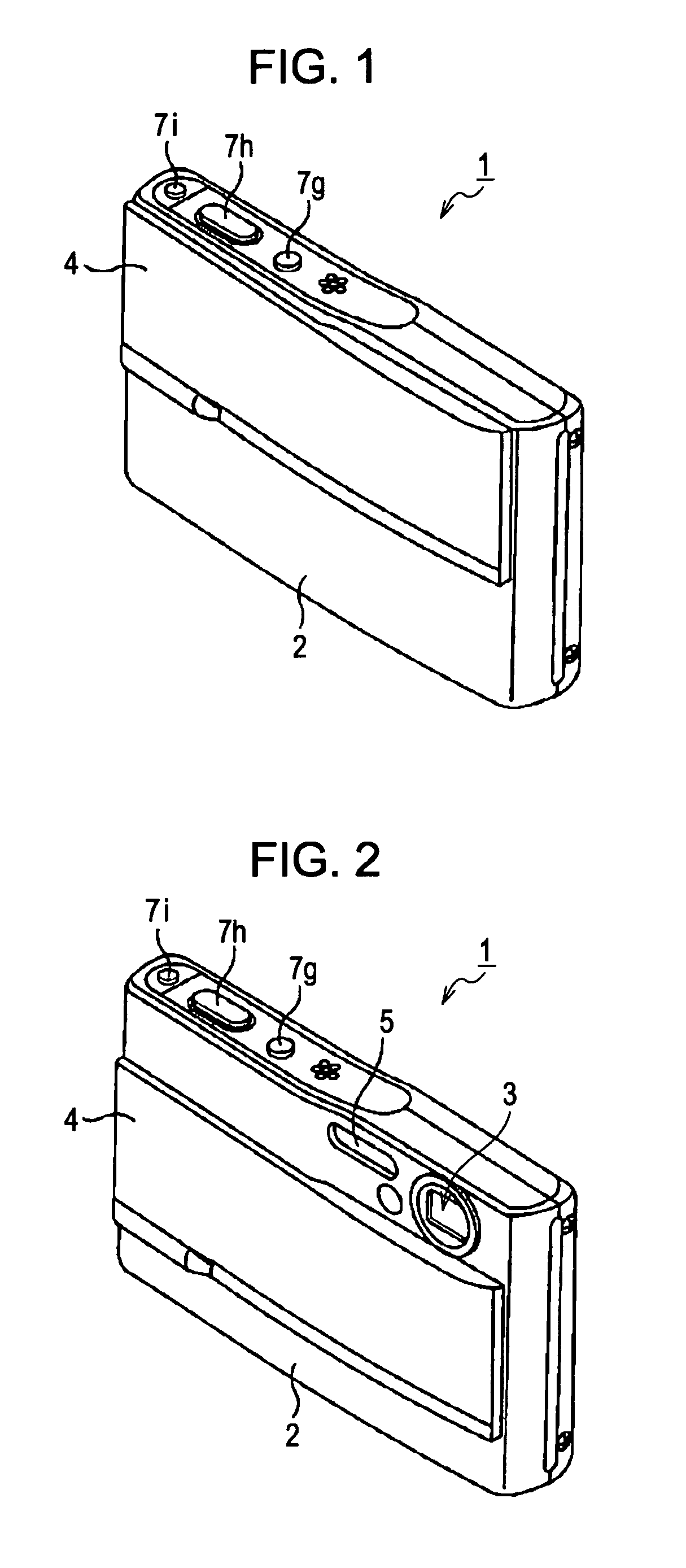
[0037]A digital still camera 1 according to an embodiment of the present invention will be described below with reference to the drawings. The digital still camera 1 will be simply referred to as “camera 1” hereinafter.

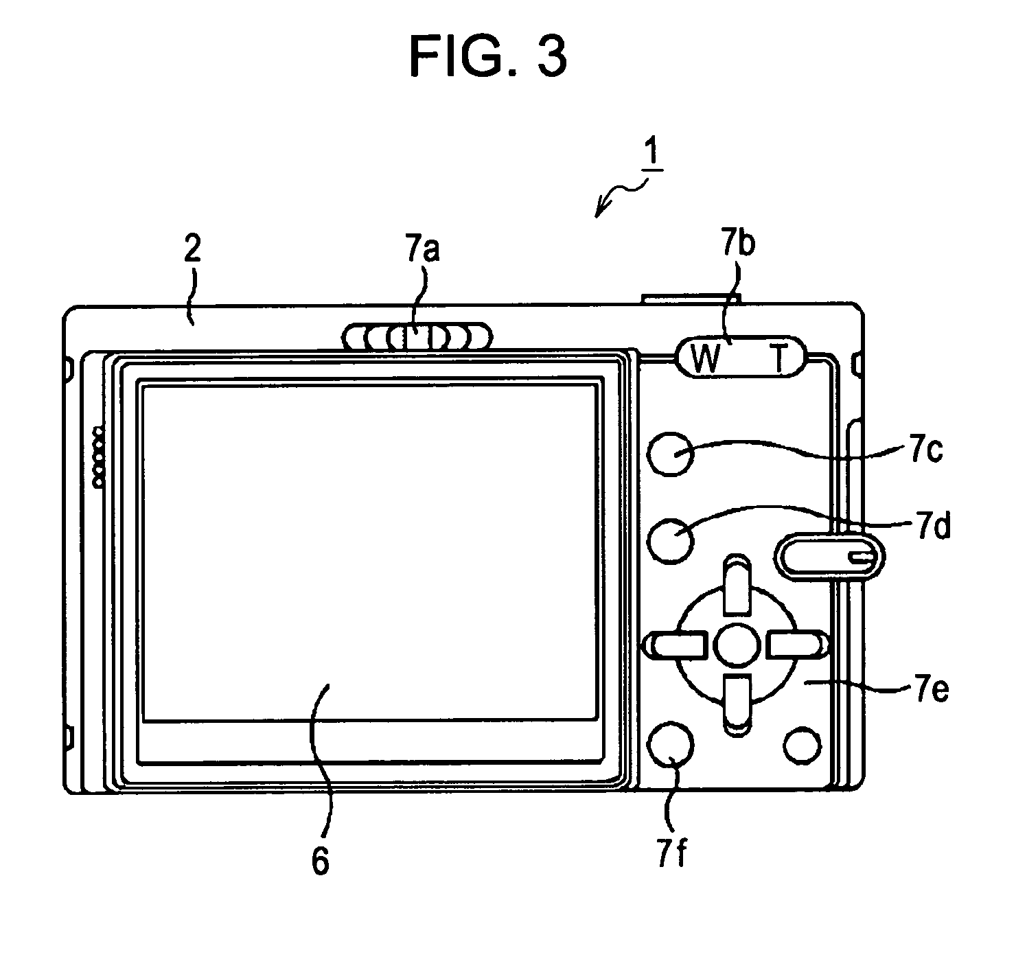
(1) Appearance Configuration of Digital Still Camera

[0038]Referring to FIGS. 1 to 3, the camera 1 according to the present embodiment of the present invention uses a semiconductor recording medium as an information recording medium and converts an optical image, corresponding to light reflected from a subject, into an electrical signal through an imager (e.g., a charge-coupled device (CCD) imager or a complementary metal-oxide semiconductor (CMOS) imager) so that the optical image can be recorded in the semiconductor recording medium or be displayed on a display unit, such as a liquid crystal display (LCD).

[0039]The camera 1 has a laterally long and low-profile camera body 2. The camera body 2 has a lens 3 in the front thereof such that the lens 3 is placed in one upp...


PUM


Abstract

An image blur correction unit includes the following elements. A holder member, holding either an imager or a lens that constitutes a part of a lens system, moves in a straight line on a plane orthogonal to the optical axis of the lens system. A movable member, attached to a frame that serves as an outermost component, supports the holder member. A guide member guides movement of the holder member relative to the frame. A driving section drives the holder member. The guide member includes a guide shaft fixed to the movable member and support portions provided for the frame, the support portions supporting the guide shaft. The movable member moves relative to the frame while being integrated with the guide shaft.

Description

CROSS-REFERENCE TO RELATED APPLICATION[0001]The present application claims priority from Japanese Patent Application JP 2008-190096 filed in the Japanese Patent Office on Jul. 23, 2008, the entire content of which is incorporated herein by reference.BACKGROUND OF THE INVENTION[0002]1. Field of the Invention[0003]The present invention relates to an image blur correction unit, a lens barrel device, and a camera apparatus each correcting an image blur caused by a vibration upon image capture, or imaging.[0004]2. Description of the Related Art[0005]Compact cameras are being requested to be further miniaturized and have higher power (magnification) and higher pixel resolution. Accordingly, this leads to an increased frequency of capturing an image blurred due to camera shake upon capturing an image of a subject. As for a mechanism for shifting an optical element to compensate for camera shake, a retractable optical system and an optical-axis bending optical system each include a mechanis...

Claims


Application Information

Patent Timeline
Patent Type & Authority Patents(United States)
IPC IPC(8): G03B17/00
CPCG03B17/00
Inventor MAEDA, IPPEINAKAYAMA, TATSUYUKI
Owner SONY CORP
Why Eureka
Try Eureka