
Luminaire

a technology of light source and light source, applied in the field of light source, can solve the problems of inefficient energy use, sensor that requires an unobstructed “view, and detrimental to the aesthetic quality of the light source, and achieve the effect of reducing energy consumption and increasing led longevity

Active Publication Date: 2011-07-26
SIGNIFY NORTH AMERICA CORP
View PDF151 Cites 36 Cited by
  • Summary
  • Abstract
  • Description
  • Claims
  • Application Information

AI Technical Summary

Benefits of technology

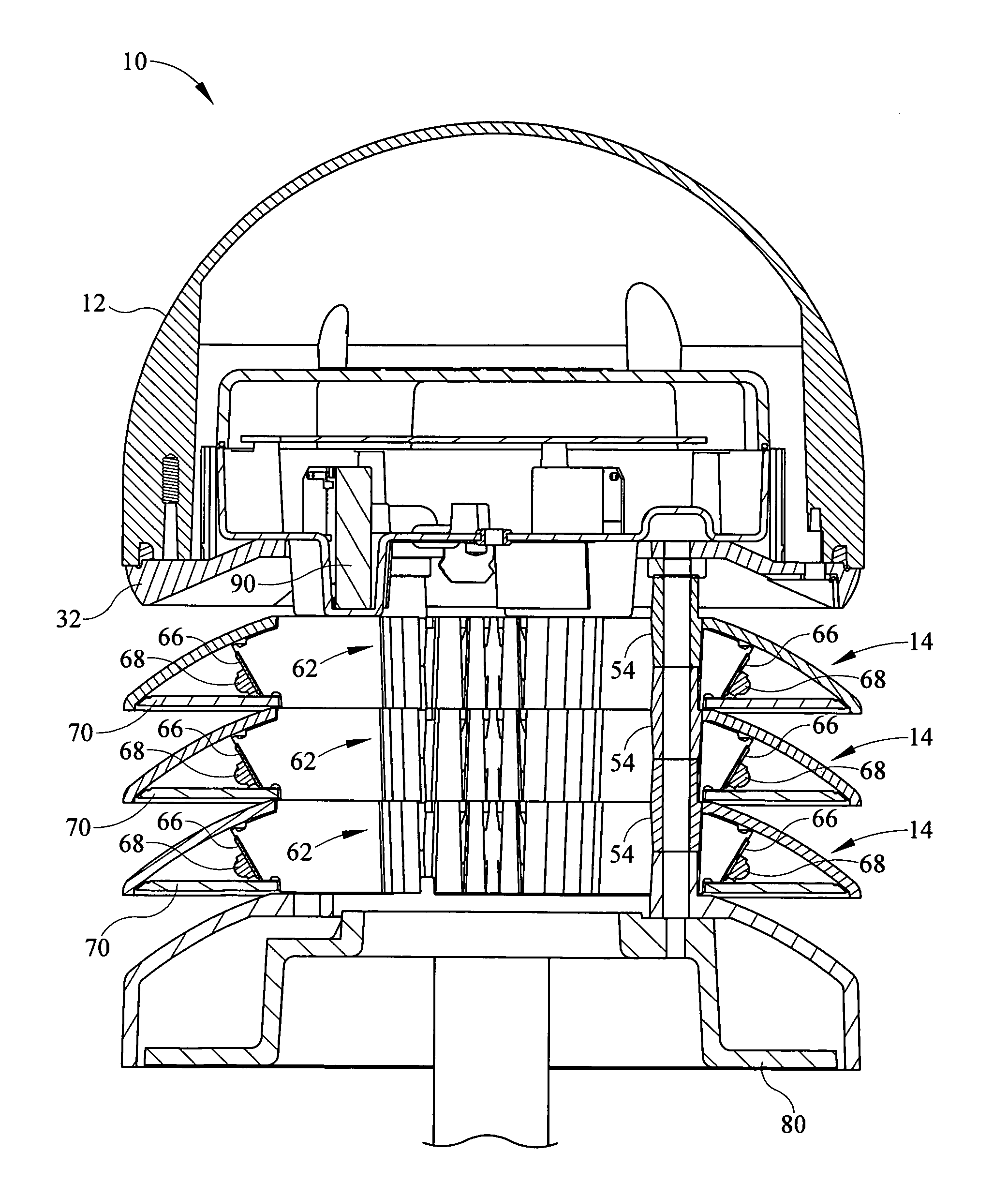
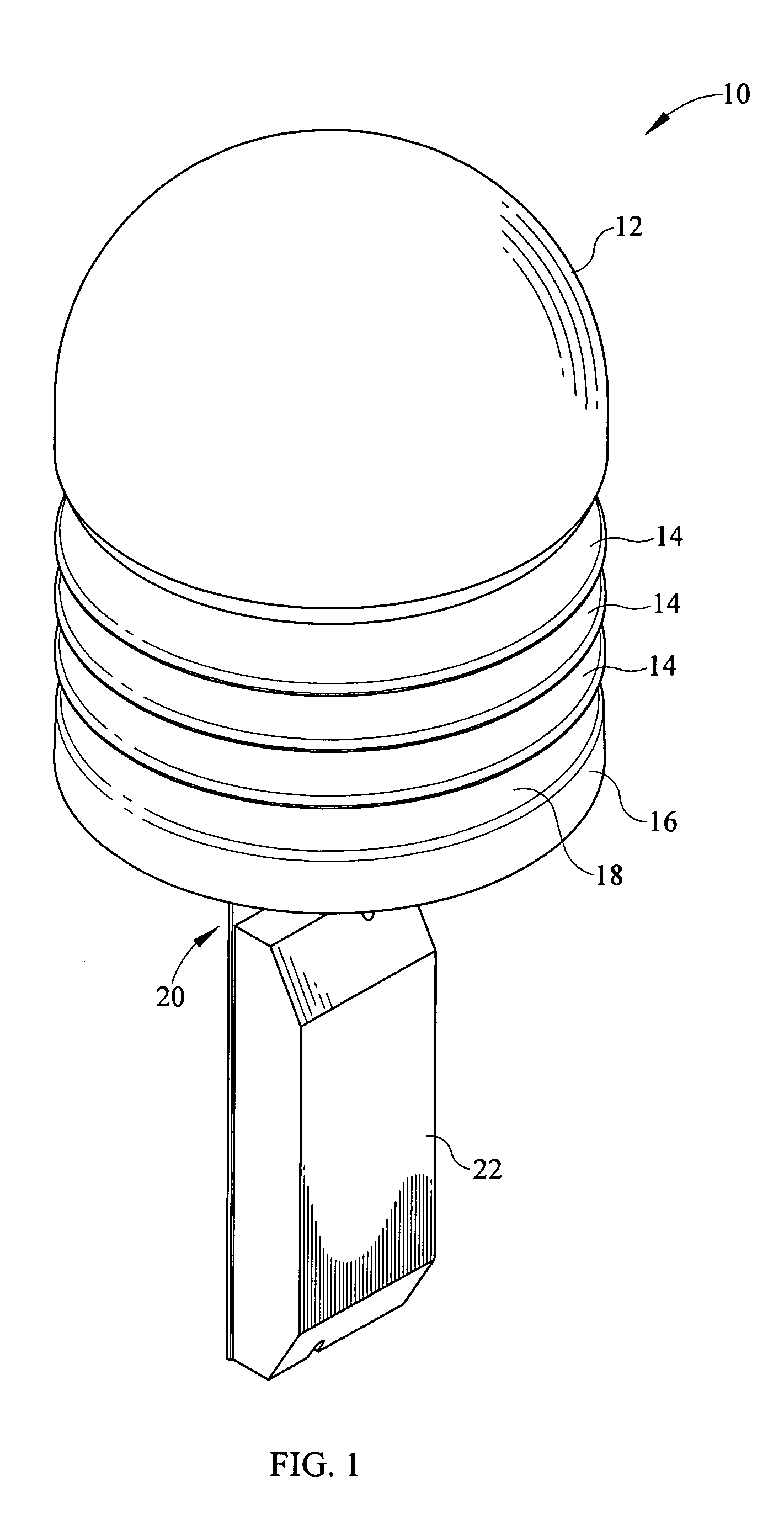
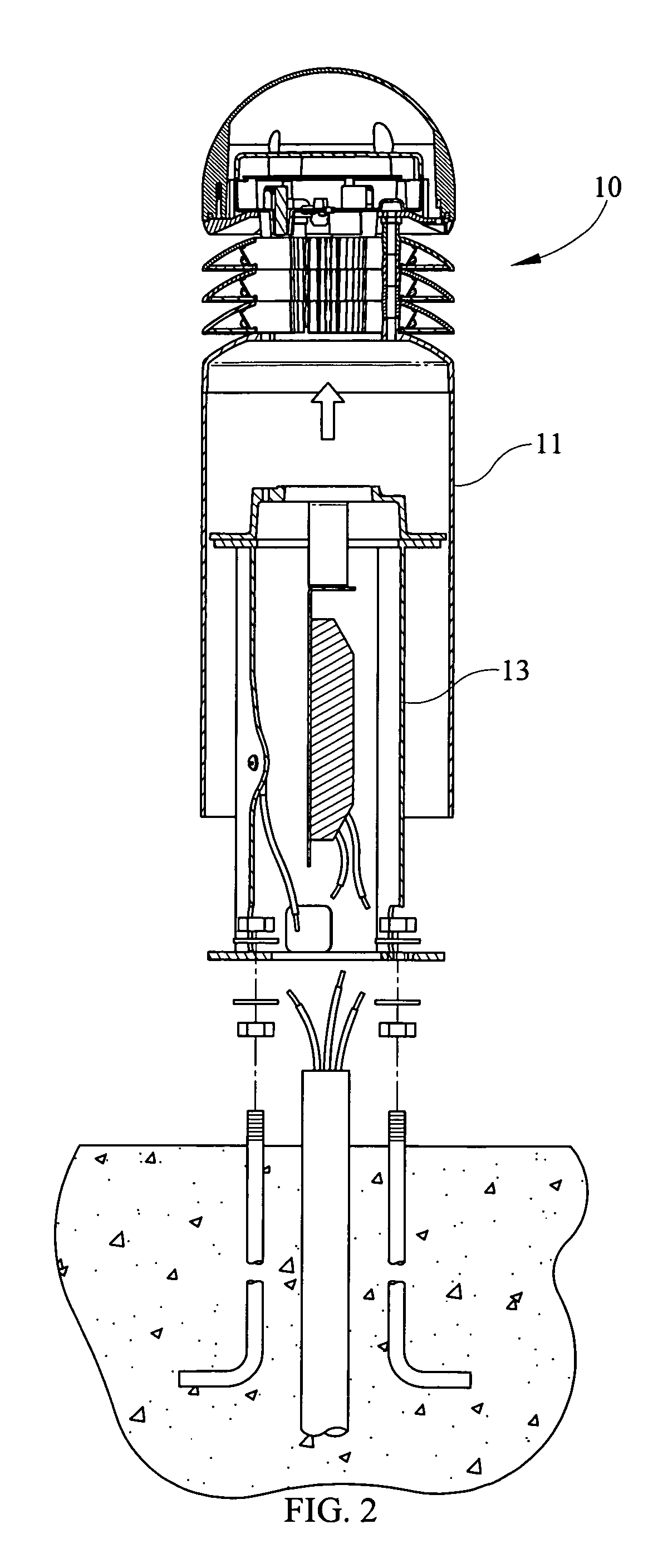
[0016]The luminaire assembly further comprising an LED driver module. The luminaire assembly wherein the luminaire is a sconce. The luminaire assembly wherein the luminaire is a bollard-type luminaire. The luminaire assembly wherein the housing is an upper dome housing. The luminaire assembly further comprising a plurality of louver light modules. The luminaire assembly wherein light emitting diodes positioned within the each of the plurality of louver light modules. The luminaire assembly wherein a LED driver module receives a signal from the microwave sensor. The luminaire assembly wherein the microwave sensor detects movement 360 degrees about the luminaire. The luminaire assembly wherein the microwave sensor having a range of up to about twenty-five (25) feet in radius. The luminaire assembly wherein the luminaire assembly provides increased LED longevity. The luminaire assembly wherein the luminaire assembly providing reduced temperature in one of the first level and the second level. The luminaire assembly wherein the luminaire assembly provides reduced energy consumption in one of the first level and the second level.

Problems solved by technology

One problem with existing bollard luminaires is their inefficient use of energy.
One problem was the use of sensors which require an unobstructed “view” of the area surrounding the bollard.
In order to provide such “view,” the sensor had to be placed outside of the bollard, which was detrimental to the aesthetic quality of the bollard.
Another problem with the existing bollard design is that existing lamp systems are not as efficient as newer forms of lighting, such as light emitting diodes (LEDs) which can emit an equivalent amount of light with less power usage.

Method used


Image

  • Luminaire
  • Luminaire
  • Luminaire

Examples


Embodiment Construction

[0030]It is to be understood that the invention is not limited in its application to the details of construction and the arrangement of components set forth in the following description or illustrated in the drawings. The invention is capable of other embodiments and of being practiced or of being carried out in various ways. Also, it is to be understood that the phraseology and terminology used herein is for the purpose of description and should not be regarded as limiting. The use of “including,”“comprising,” or “having” and variations thereof herein is meant to encompass the items listed thereafter and equivalents thereof as well as additional items. Unless limited otherwise, the terms “connected,”“coupled,” and “mounted,” and variations thereof herein are used broadly and encompass direct and indirect connections, couplings, and mountings. In addition, the terms “connected” and “coupled” and variations thereof are not restricted to physical or mechanical connections or couplings...


PUM


Abstract

A luminaire assembly comprises a housing, a plurality of light emitting diodes disposed within the housing, a microwave sensor disposed within the housing for detecting occupants in an area adjacent the housing, wherein the microwave sensor is in electrical communication with the light emitting diodes, and wherein the light emitting diodes are driven at a first light level and in response to the microwave sensor at a second light level.

Description

CROSS REFERENCES TO RELATED APPLICATIONS[0001]None.STATEMENT REGARDING FEDERALLY SPONSORED RESEARCH OR DEVELOPMENT[0002]None.REFERENCE TO SEQUENTIAL LISTING, ETC[0003]None.BACKGROUND[0004]1. Field of the Invention[0005]The present invention relates generally to a luminaire. More particularly, the invention relates to a luminaire having an occupancy sensor causing demand response bi-level illumination of light emitting diodes (LEDs).[0006]2. Description of the Related Art[0007]Bollards are protective structures which are generally located around buildings or machines at industrial, commercial, or institutional premises. They are believed to be named because their shape tends to resemble posts or “bollards” used at wharfs, and around which mooring lines are fastened. Bollards are generally known as having cement or extruded metal posts to protect an exterior portion of a building or the like. When metal bollard posts are utilized, they may be fastened to structures already placed in t...

Claims


Application Information

Patent Timeline
Patent Type & Authority Patents(United States)
IPC IPC(8): F21V23/04F21V29/00
CPCF21S8/083F21V23/0485F21V15/005F21Y2101/02F21V5/04F21V23/023F21V23/026F21V23/0471F21Y2113/00F21V29/74F21Y2103/33F21Y2105/10F21Y2115/10G08B7/064
Inventor SCHACH, JOHN WILLIAMPERREIRA, DONALD MANUELBOISSEVAIN, CHRIS
Owner SIGNIFY NORTH AMERICA CORP
Learn More