
Patient bed with force generator to assist or effect movement of a device plug in a bed socket

a force generator and patient bed technology, applied in the field of patient beds, can solve the problems of contact deformation, one or both arms breaking off, and the unplugging is very labor-intensive and consequently difficult, and achieve the effect of safe operation

Inactive Publication Date: 2011-07-26
SIEMENS AG
View PDF11 Cites 7 Cited by
  • Summary
  • Abstract
  • Description
  • Claims
  • Application Information

AI Technical Summary

Benefits of technology

[0006]An object of the present invention is to provide a patient bed of the above type that is improved by exhibiting a safely functioning movement aid for moving the plug relative to the socket.
[0009]Depending on the design of the automatic movement aid, the insertion or unplugging of the plug consequently becomes significantly simpler and more comfortable for the user and damage to the patient bed is safely avoided.
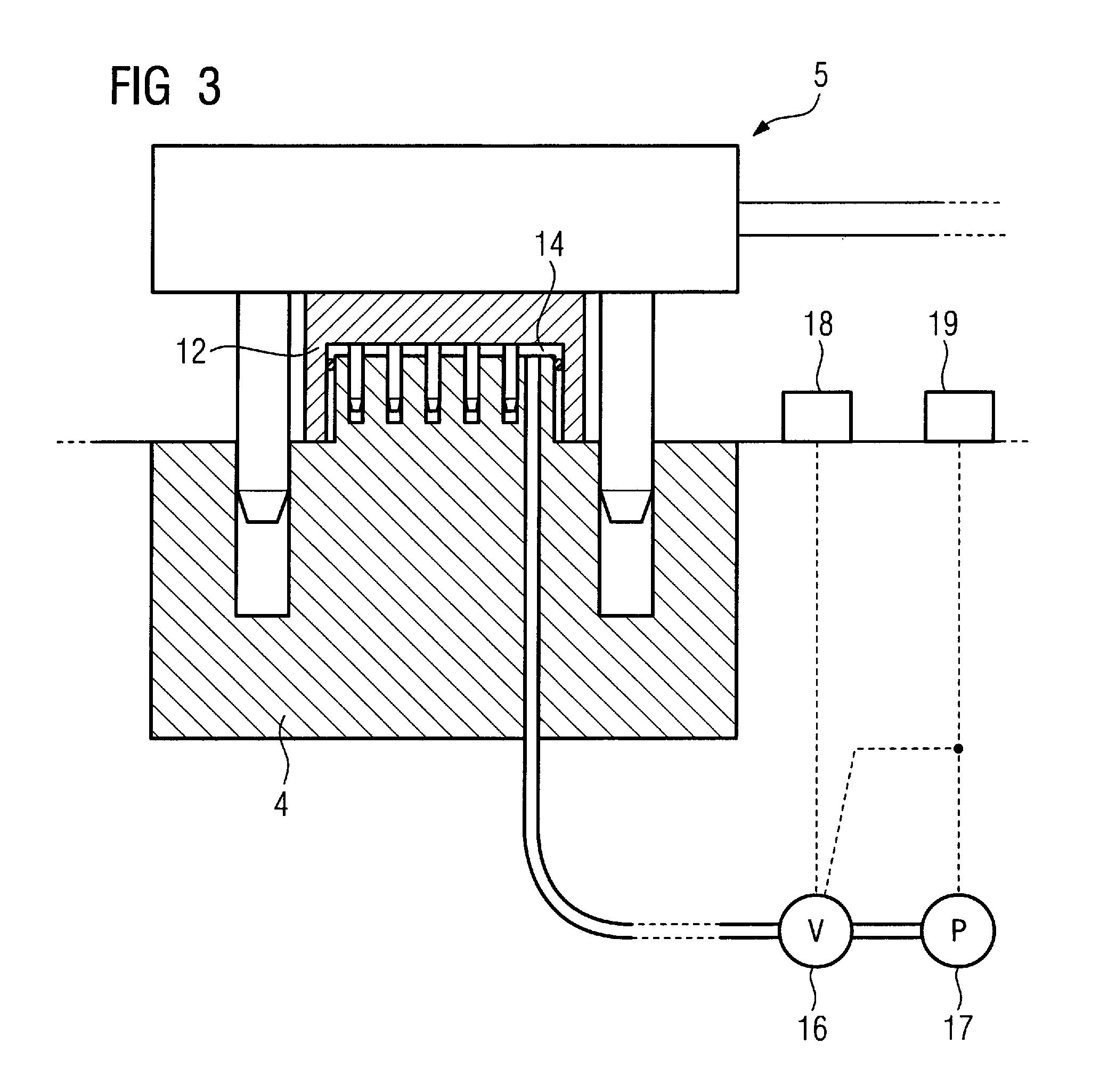
[0015]It is particularly appropriate for a number of sockets to be provided at the bed, which is typically the case since various local coils are to be arranged and contacted at different positions. These multiple sockets are now appropriately connected via separate conduits with a central pump that, as described, is typically already integrated at the bed, with a valve for closing the conduit in the absence of a plug in the associated plug connection being associated with each conduit. It can thereby be ensured that the pump does not continuously draw air via the sockets when the valves are closed due to no detected plug, which could lead to a noise disturbance.
[0019]Usually the user does not have to rush to remove the individual plugs from the corresponding sockets when the examination has ended and the patient is moved out from the magnetic resonance apparatus. However, an emergency situation may arise, for example in the case of a quench of the superconducting magnet, in which situation the patient must be brought out from the examination chamber as quickly as possible. However, the patient is more or less immovably “strapped” to the patient bed by the one or more local coils. If the operator must now separately pull each coil plug (and given multiple or large-area local coils it is not unusual to have a considerable number of sockets occupied with plugs), the entire procedure takes a substantial amount of time, which is not acceptable in this situation. In order to counteract this, in an embodiment of the invention a number of sockets at the bed, provided with a respective force-generators having such a force generator associated therewith, are coupled like a network so that given actuation of a central control element all plugged-in plugs can be manipulated in common to effect a common unplugging. This embodiment allows the prompt unplugging of all plugged-in plugs at the point in time of the operation of the central control element, such that all local coils are immediately detached from the patient bed in terms of their electrical contact. The local coils then can be removed quickly from the bed without further measures so that the patient can descend from the patient bed. Only a network-like coupling of the force generators with a central control element is required with, the particular embodiment of this central control element ultimately depending on whether the unplugging operates pneumatically or electromechanically.

Problems solved by technology

While the plugging movement (in which the plug is, for example, placed vertically into the socket from above) is still relatively simple to effect by medical technology personnel, the unplugging is very labor-intensive and consequently difficult due to the very firm accommodation of the plug.
The unplugging frequently is accomplished by jiggling somewhat at the plug or twisting the plug in order to loosen it, which can lead to deformation of the contacts if undertaken frequently.
It sometimes occurs that one or both arms break off due to the strong loading of the lever arms, or that the cover lid is over-pressured and is consequently ripped from its pivot bearing.

Method used


Image

  • Patient bed with force generator to assist or effect movement of a device plug in a bed socket
  • Patient bed with force generator to assist or effect movement of a device plug in a bed socket
  • Patient bed with force generator to assist or effect movement of a device plug in a bed socket

Examples


Embodiment Construction

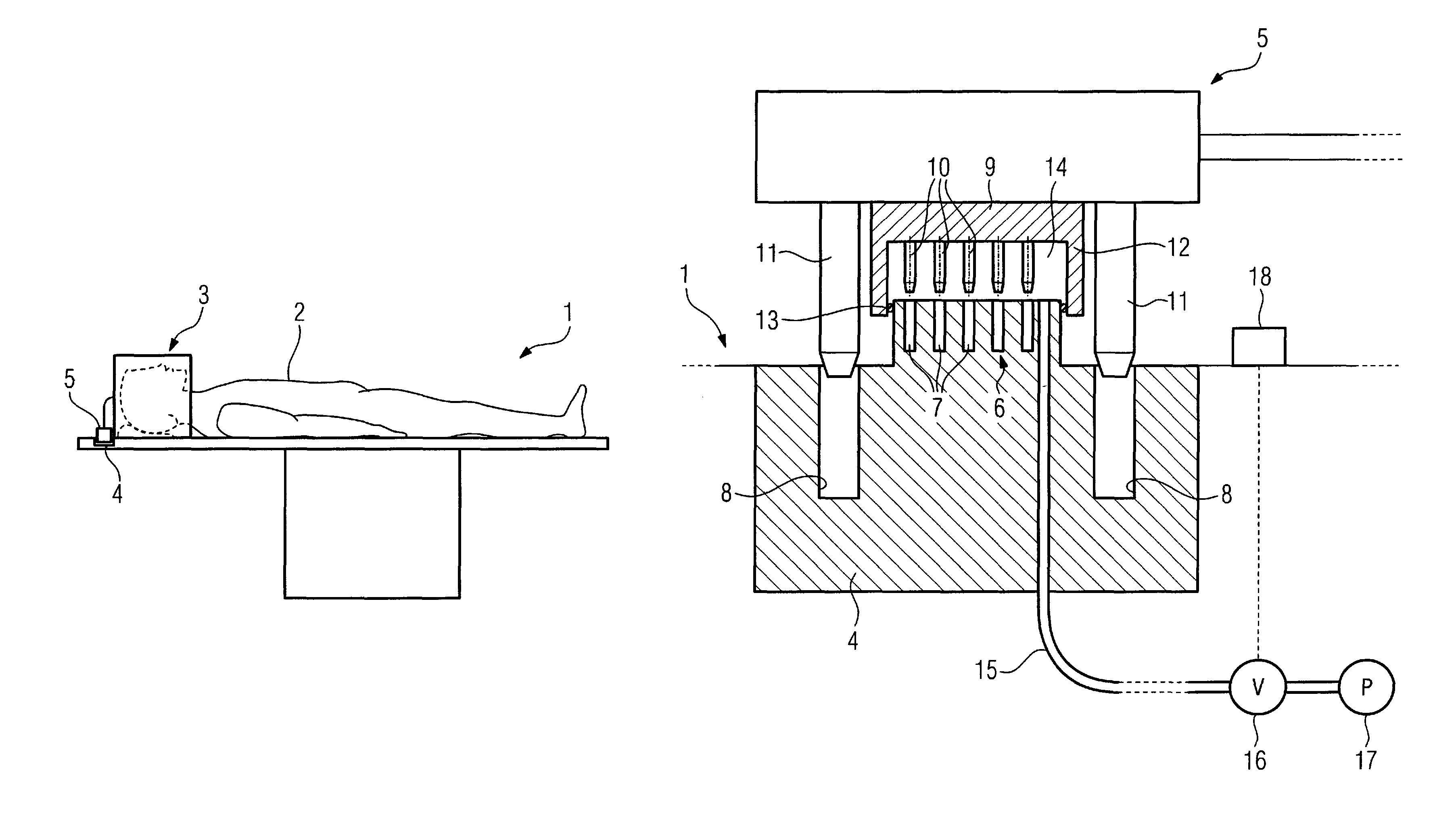
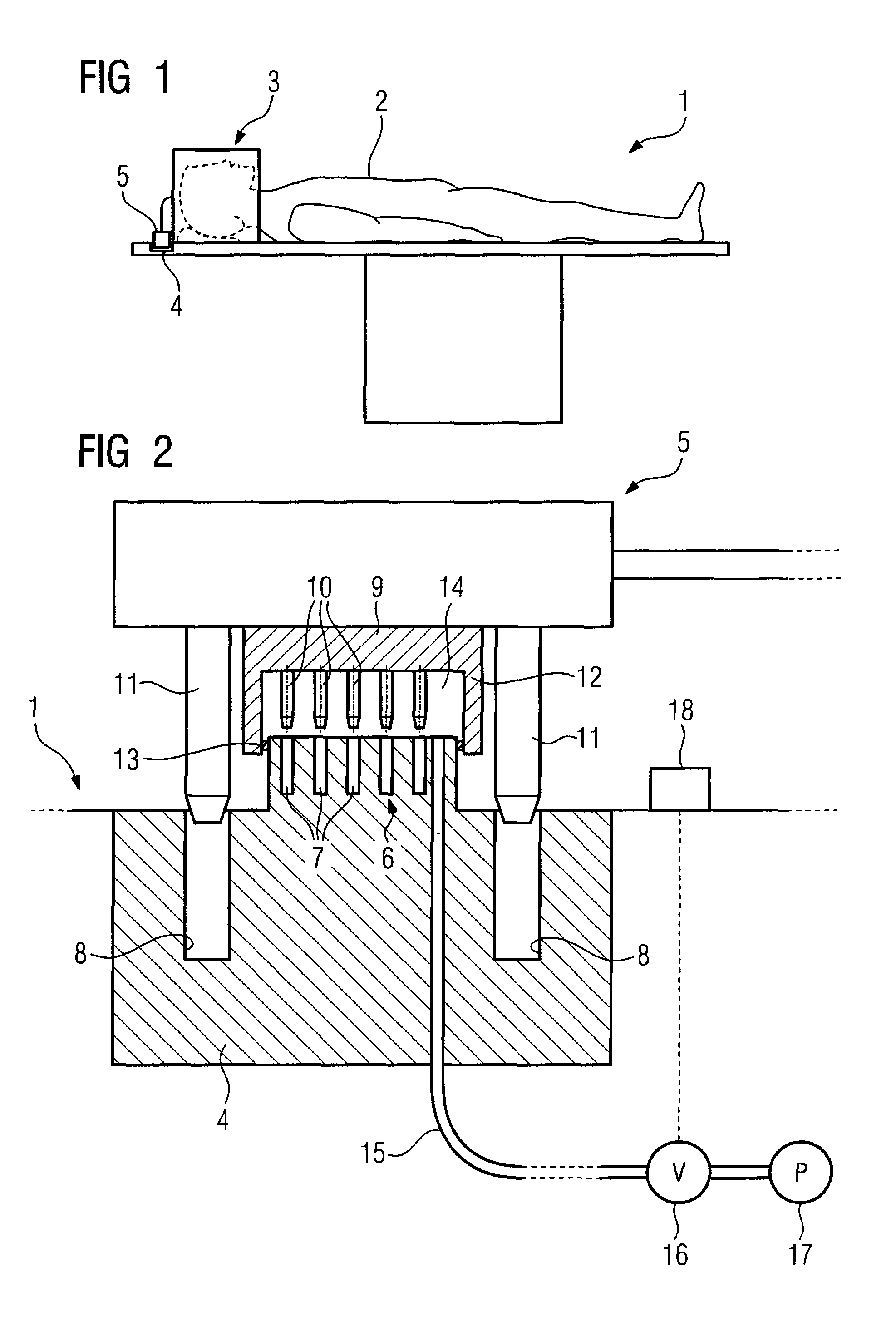
[0031]FIG. 1 shows an inventive patient bed 1 on which a patient 2 is arranged. The patient bed 1, which is suitable for a magnetic resonance apparatus, can be displaced vertically in a known manner and the table can be moved horizontally. In the shown example, a local coil 3 (here in the form of a head coil) is arranged at the patient bed 1. For electrical contacting, a socket 4 into which a plug 5 of the local coil 3 is inserted is provided at the patient bed 1. The signal transmission of the image signals acquired by the local coil 3 ensues to a control and processing device (not shown in detail).

[0032]FIG. 2 shows a socket-plug arrangement in an enlarged representation. Shown is a section of the patient bed 1 in the region of the socket 4. This has a contact segment 6 with a number of individual socket contacts 7 that are connected with electrical conductors (not shown). Also provided are two plug guides 8 in the form or two recesses.

[0033]Also shown is the plug 5 that likewise ...


PUM


Abstract

A patient bed, in particular for a magnetic resonance apparatus, has at least one socket for accommodation of a plug of a device (in particular a local coil) to be arranged at the patient bed. A generation of a force generator that automatically assists or effects the insertion or the unplugging of the plug is built into the socket or is associated with the socket.

Description

BACKGROUND OF THE INVENTION[0001]1. Field of the Invention[0002]The present invention concerns a patient bed, in particular for a magnetic resonance apparatus, of the type having at least one socket for accepting a plug of a device (in particular a local coil) to be arranged at the patient bed.[0003]2. Description of the Prior Art[0004]Primarily for patient beds used in magnetic resonance apparatuses, it is necessary to use special local coils for image acquisition of specific body regions. These local coils are typically arranged at the patient bed and are appropriately positioned relative to the patient. Signals originating from the examination or measurement volume are acquired by the local coil, and these signals are provided by signal conductors to the control and processing device of the magnetic resonance apparatus for image processing. For this purpose, a socket into which a plug is inserted is provided at the bed, and the coil signals are transferred to the conductor connec...

Claims


Application Information

Patent Timeline
Patent Type & Authority Patents(United States)
IPC IPC(8): G01V3/00
CPCA61B5/0555H01R13/629H01R13/635H01R13/637A61G2210/50A61B5/055
Inventor FELD, PETERFISCHER, HUBERTUSSCHNELL, WILFRIED
Owner SIEMENS AG
Learn More