Phase change material thermal power generator

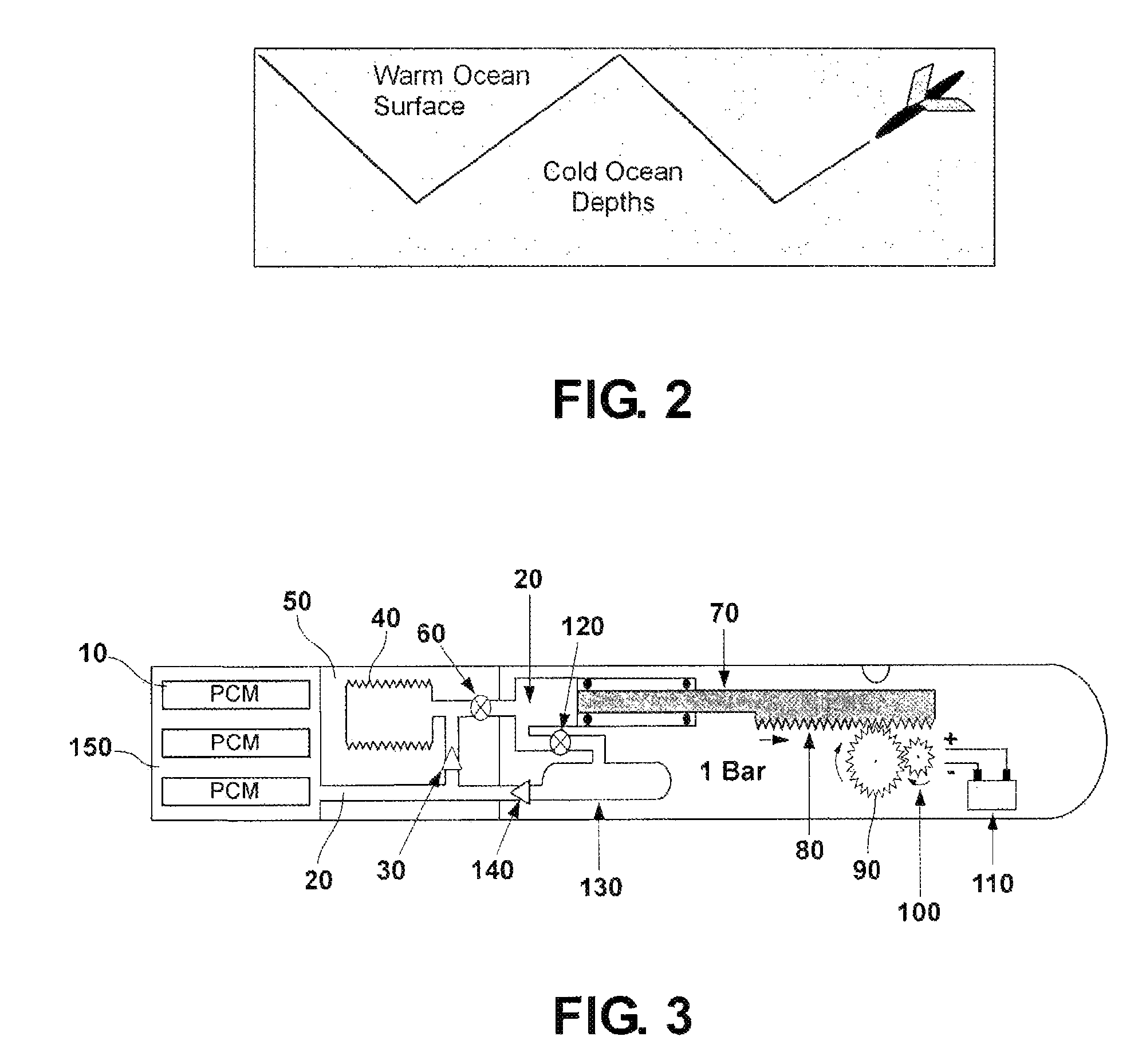
a technology of phase change material and thermal power generator, which is applied in the field of power generators, can solve the problems of inefficient, complicated and expensive fabrication, and the device of fig. 3 is too heavy, and the cost of fabrication is both complicated and expensiv

Active Publication Date: 2011-08-02
CALIFORNIA INST OF TECH
View PDF12 Cites 11 Cited by
  • Summary
  • Abstract
  • Description
  • Claims
  • Application Information

AI Technical Summary

Problems solved by technology

The device of FIG. 3 proved to be too heavy, inefficient, complicated and expensive to fabricate.
Because the sys

Method used


Image

  • Phase change material thermal power generator
  • Phase change material thermal power generator
  • Phase change material thermal power generator

Examples


Embodiment Construction

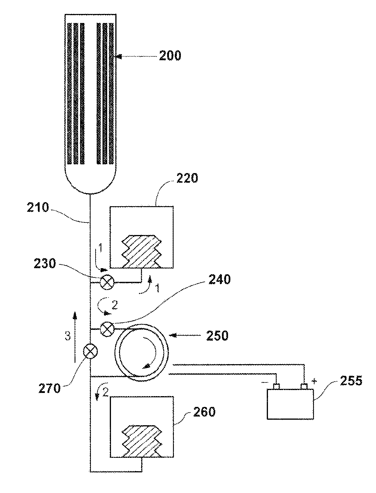
In accordance with the present disclosure, a simplified system is provided with the use of a hydraulic motor to replace the piston and a generator to produce electricity.

As shown in FIG. 4, the PCM (200) melting causes the hydraulic fluid (210) to be stored in a gas spring bellows (220) (e.g., at a pressure of 3000 psia) when the fluid is flowed past valve (230), see path 1. When power is desired, valve (240) is opened and the fluid passes through a hydraulic motor (250) (path 2), thus eliminating all the pistons and gears of FIG. 3 above, and allowing a more simple, efficient and lightweight operation and charging of battery (255).

The battery (255) can be used to power scientific measuring equipment, communications, imaging, etc. It can also be used for electrically-powered buoyancy control and for directional control equipment.

Applicants have noted that a commercially available hydraulic motor can replace the complicated components represented by (20), (70), (80), and (90) in FIG....


PUM


Abstract

An energy producing device, for example a submersible vehicle for descending or ascending to different depths within water or ocean, is disclosed. The vehicle comprises a temperature-responsive material to which a hydraulic fluid is associated. A pressurized storage compartment stores the fluid as soon as the temperature-responsive material changes density. The storage compartment is connected with a hydraulic motor, and a valve allows fluid passage from the storage compartment to the hydraulic motor. An energy storage component, e.g. a battery, is connected with the hydraulic motor and is charged by the hydraulic motor when the hydraulic fluid passes through the hydraulic motor. Upon passage in the hydraulic motor, the fluid is stored in a further storage compartment and is then sent back to the area of the temperature-responsive material.

Description

FIELDThe present disclosure related to power generators. In particular, it relates to a phase change material thermal power generator.BACKGROUNDThere are many thousands of ocean research buoys that presently bob up and down in the world's oceans, performing scientific research on temperature, salinity, global warming, ocean currents, and pollution. A graph of recent locations of these battery-powered buoys is shown in FIG. 1. At present, each buoy, which costs about $25K each, can travel between sea-level and about 1000 to 2000-m depths, and they are considered disposable after the batteries wear out, typically after some months of use.There are also many gliding submersibles for the Navy and for research purposes. Each of these gliding vehicles cost about $100K, and the batteries last a period of months before these vessels are also disposed after the batteries run out. A typical gliding path is shown in FIG. 2 and may cover depths from sea level to about 700-m.For most places in t...

Claims


Application Information

Patent Timeline
IPC IPC(8): F03G7/04
CPCF03G7/05Y02E10/34Y02E10/30
Inventor JONES, JACK A.CHAO, YIVALDEZ, THOMAS I.
Owner CALIFORNIA INST OF TECH
Why Eureka
Try Eureka