Imaging apparatus, imaging method, storage medium, and integrated circuit

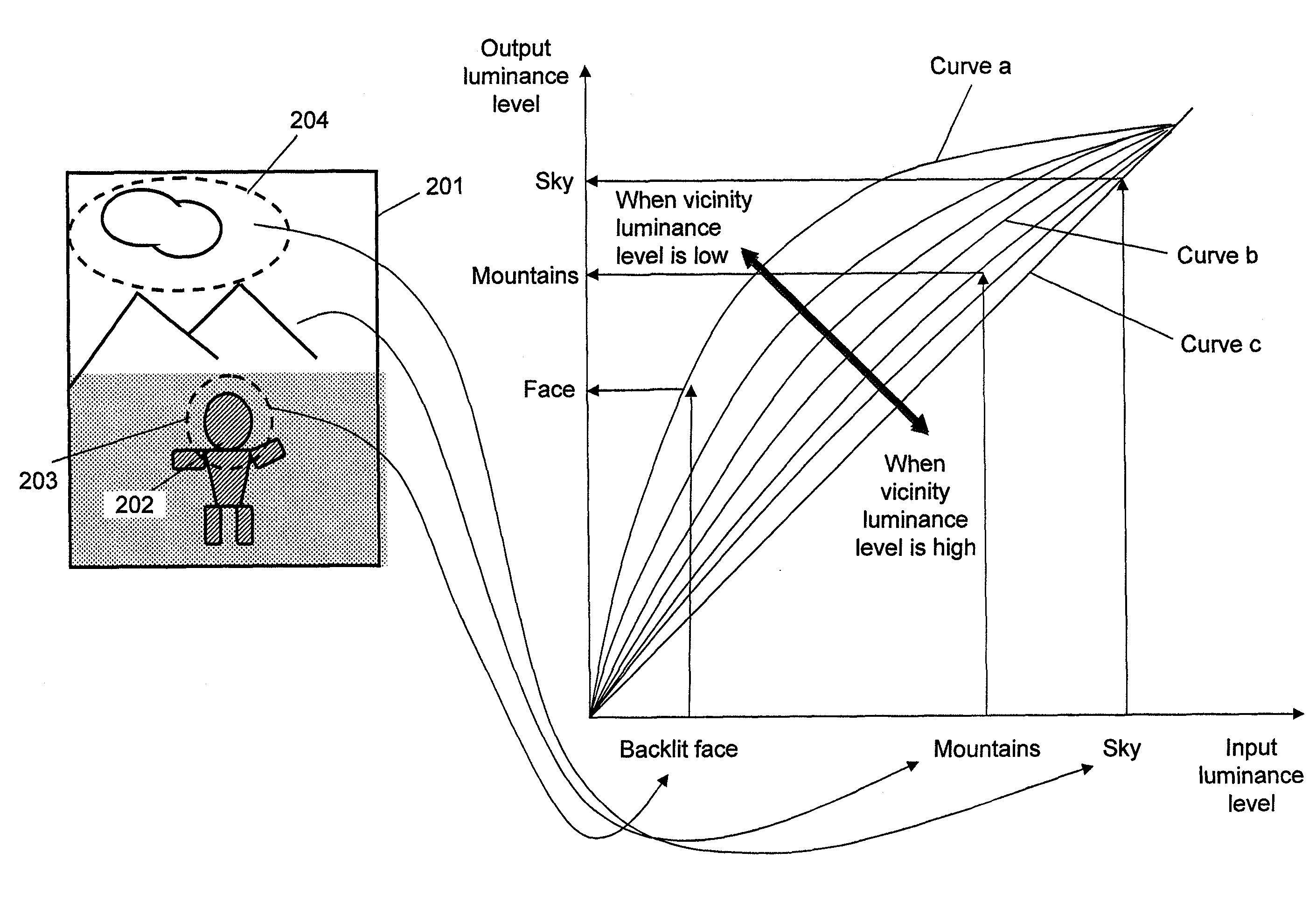
a technology of imaging apparatus and integrated circuit, which is applied in the direction of exposure control, instruments, television systems, etc., can solve the problems of inability to reproduce color, overexposure of the sky increased luminance level of the person region of the captured image, so as to increase the luminance level of the dark image region

Active Publication Date: 2011-08-02
5G NUMULTIMEDIA LTD
View PDF7 Cites 9 Cited by
  • Summary
  • Abstract
  • Description
  • Claims
  • Application Information

AI Technical Summary

Benefits of technology

[0084]The imaging method has the same advantageous effects as the imaging apparatus of the first aspect of the present invention.
[0085]A fifteenth aspect of the present invention provides a storage medium storing a program enabling a computer to implement an imaging method used in an imaging apparatus that includes an optical system with a light amount adjustment function operable to focus light from a subject and an imaging unit operable to read an optical image of the subject that is formed with the light focused by the optical system and obtain the read optical image as an image signal. The program enables the computer to perform a backlight correction process, an instruction determination process, and a control process.
[0086]In the backlight correction process, backlight correction of the image signal is performed by performing tone conversion of converting a tone of a processing target pixel that is included in an image formed by the image signal using a conversion characteristic that is selected differently according to a spatial position of the processing target pixel in the image. The tone conversion is performed in a manner to at least increase a luminance level of a dark image region of the image. In the instruction determination process, whether an instruction signal instructing to start the backlight correction performed in the backlight correction process is received is determined. In the control process, the backlight correction is started in the backlight correction process based on the instruction signal output in the instruction determination process, and an amount of light in the optical system is adjusted by decreasing an exposure light amount of the imaging unit by a predetermined amount.
[0087]The storage medium storing the program has the same advantageous effects as the imaging apparatus of the first aspect of the present invention.
[0088]A sixteenth aspect of the present invention provides an integrated circuit used in an imaging apparatus that includes an optical system with a light amount adjustment function operable to focus light from a subject and an imaging unit operable to read an optical image of the subject that is formed with the light focused by the optical system and obtain the read optical image as an image signal. The integrated circuit includes a backlight correction unit, an instruction unit, and a control unit.
[0089]The backlight correction unit performs backlight correction of the image signal by performing tone conversion of converting a tone of a processing target pixel that is included in an image formed by the image signal using a conversion characteristic that is selected differently according to a spatial position of the processing target pixel in the image. The tone conversion is performed in a manner to at least increase a luminance level of a dark image region of the image. The instruction unit outputs an instruction signal instructing to start the backlight correction performed by the backlight correction unit. The control unit starts the backlight correction based on the instruction signal output from the instruction unit, and adjusts an amount of light in the optical system by decreasing an exposure light amount of the imaging unit by a predetermined amount.

Problems solved by technology

In the case (B), the luminance level of the person region of the captured image is increased, whereas the sky region of the captured image is completely overexposed and fails to reproduce color.
In the case (C), however, the sky region of the captured image is overexposed slightly, whereas the person region of the captured image is not sufficiently bright.
In this manner, the imaging apparatus fails to capture an image with a satisfactory image quality even in the case (C).
In the image captured using the backlight correction mode, the person would be bright but the background would be completely overexposed and fail to reproduce color.
As a result, the image captured using the backlight correction mode may fail to have a high image quality.
However, the backlight correction is not performed in an appropriate manner through the tone conversion performed using the tone curve X. The image resulting from the tone conversion performed using the tone curve X would be an unnatural image with an extremely low contrast of only intermediate tones (for example, the tones of an image region indicated by a circle drawn with a dotted line in FIG. 18) as shown in FIG. 2 of Non-Patent Citation 1.
As a result, the background sky region may easily be overexposed and fail to reproduce color (the tones of a highlight region, such as a sky region, may easily be saturated).
Therefore, the tone conversion (backlight correction) using the tone curve Y cannot be used to perform drastic backlight correction.
However, a highlight region of the image resulting from such tone conversion would be too bright in the same manner as in the case (B).
For example, a sky region of the image resulting from the tone conversion performed using such a curve (tone conversion characteristic curve) may be overexposed and fail to reproduce color (a sky region may lose its tones).
Also, the image resulting from such tone conversion may fail to have a sufficiently high contrast across the entire image.
As a result, even the tone conversion (backlight correction) performed using the curve (tone conversion characteristic curve) with which the luminance level of not only a dark region but also an image region with an intermediate luminance level is increased cannot be used to perform drastic backlight correction.

Method used


Image

  • Imaging apparatus, imaging method, storage medium, and integrated circuit
  • Imaging apparatus, imaging method, storage medium, and integrated circuit
  • Imaging apparatus, imaging method, storage medium, and integrated circuit

Examples


first embodiment

1.1 Structure of the Imaging Apparatus

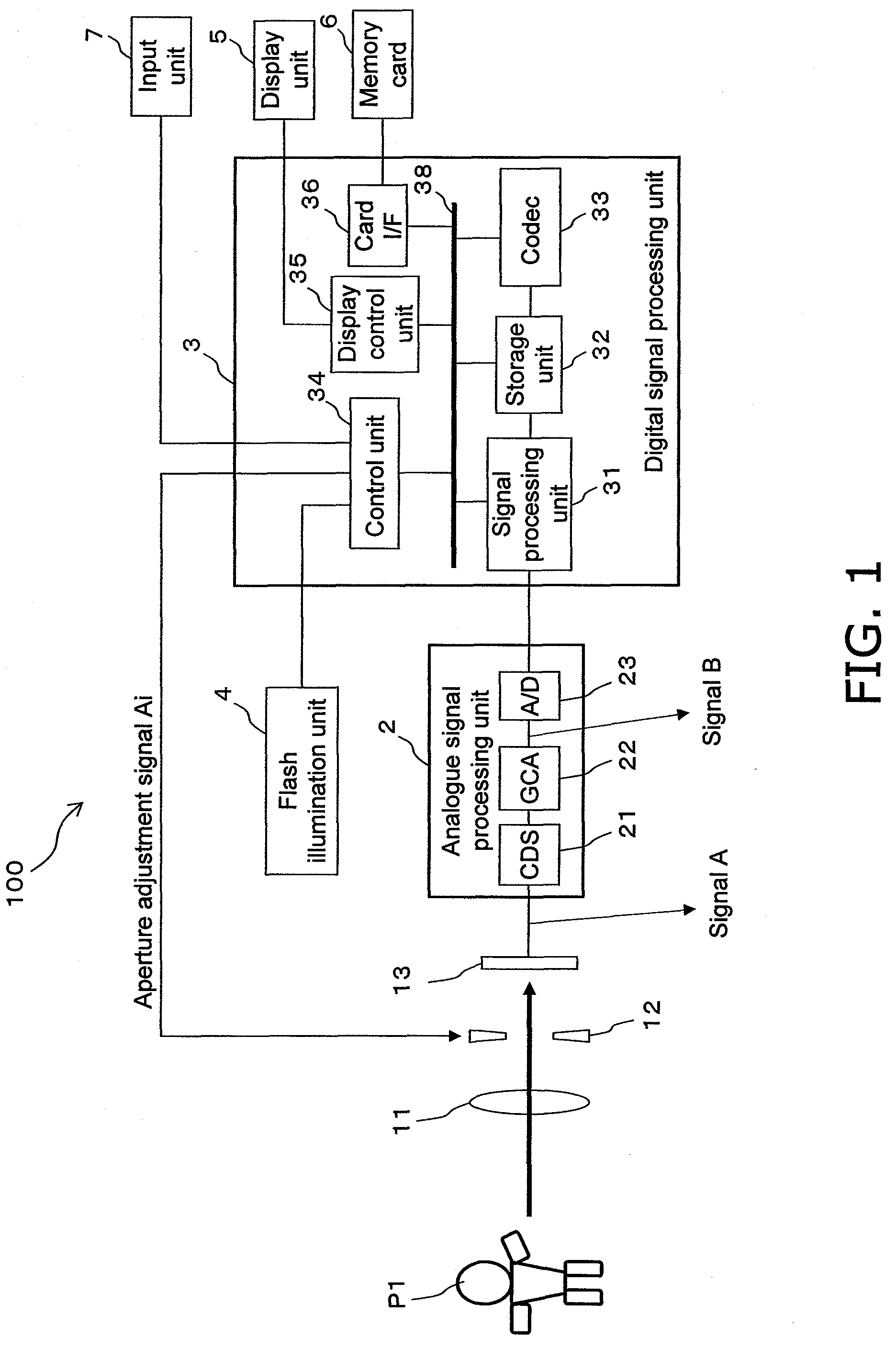
[0137]FIG. 1 shows the schematic structure of an imaging apparatus 100 according to a first embodiment of the present invention.

[0138]The imaging apparatus 100 includes an optical system (an imaging lens 11, an aperture 12, an imaging unit 13, a flash illumination (strobe light) unit 4), an analogue signal processing unit 2, and a digital signal processing unit 3. The imaging apparatus 100 also includes a memory card 6, a display unit (for example a liquid crystal display) 5, and an input unit (user interface) 7, which may be modified freely. The imaging apparatus 100 also includes a bus 38, which connects the functional units of the digital signal processing unit 3. In the present embodiment, the functional units of the digital signal processing unit 3 are connected by the bus 38 as shown in FIG. 1. However, the functional units of the digital signal processing unit 3 may not necessarily be connected via the bus but may be connected directly to...

first modification

[0230]A first modification of the present embodiment will now be described.

[0231]FIG. 10 shows a signal processing unit 31A according to the first modification.

[0232]The signal processing unit 31A of the present modification differs from the signal processing unit 31 (see FIG. 2) of the first embodiment in that the signal processing unit 31A additionally includes an image characteristic amount extraction unit 210 and a photometry unit 104 of the signal processing unit 31A divides an image into a plurality of image regions and outputs a photometric value corresponding to each divisional image region. The other structure of the signal processing unit 31A is the same as the structure of the signal processing unit 31 of the first embodiment described above. Also, the imaging apparatus according to the first modification is the same as the imaging apparatus 100 of the first embodiment except that the signal processing unit 31 is replaced by the signal processing unit 31A. Thus, the imagi...

second modification

[0274]An imaging apparatus according to a second modification of the present embodiment will now be described.

[0275]FIG. 13 is a functional block diagram of a signal processing unit 31B and a control unit 34 included in the imaging apparatus according to the present modification.

[0276]The imaging apparatus of the present modification includes a signal processing unit 31B instead of the signal processing unit 31 (or the signal processing unit 31A) included in the imaging apparatus 100 of the first embodiment. The other structure of the imaging apparatus of the present modification is the same as the structure of the imaging apparatus 100 of the first embodiment, and will not be described in detail.

[0277]As shown in FIG. 13, the signal processing unit 31B includes a visualization processing unit 400B instead of the local backlight correction unit 101 and the interior-division processing unit 103 of the signal processing unit 31. An image characteristic amount extraction unit 210 is th...


PUM


Abstract

An imaging apparatus for capturing a moving image performs backlight correction of an image and outputs a natural image. The imaging apparatus electronically captures an image of a subject. An optical system has a light amount adjustment function. An imaging unit reads an optical image of the subject that is formed by the optical system. An A / D converter subjects an output of the imaging unit to A / D conversion. A backlight correction unit converts the tones of an image read by the A / D converter using a conversion characteristic selected differently according to a spatial position and at least increases the luminance level of a dark region of the image. An instruction unit instructs to start backlight correction. A control unit operates the backlight correction unit based on an instruction signal output from the instruction unit, and decreases an exposure light amount of the optical system by a predetermined amount.

Description

[0001]This application claims priority to Japanese Patent Application No. 2007-237730 filed on Sep. 13, 2007 and priority to Japanese Patent Application No. 2008-169430 filed on Jun. 27, 2008. The entire disclosure of Japanese Patent Application No. 2007-237730 filed on Sep. 13, 2007 and the entire disclosure of Japanese Patent Application No. 2008-169430 filed on Jun. 27, 2008 are hereby incorporated herein by reference.BACKGROUND OF THE INVENTION[0002]1. Field of the Invention[0003]The present invention relates to an imaging apparatus that appropriately captures an image of a scene in which a main subject is dark and a scene with a large dynamic range, an imaging method used in the imaging apparatus, an integrated circuit that functions as the imaging apparatus, and a storage medium storing an imaging program used in the imaging apparatus.[0004]2. Description of the Related Art[0005]Imaging apparatuses, such as a digital still camera for capturing still images and a digital video ...

Claims


Application Information

Patent Timeline
Patent Type & Authority Patents(United States)
IPC IPC(8): H04N5/238H04N5/243H04N5/20
CPCG03B7/091H04N5/23219H04N5/238H04N5/243H04N5/2351G06K9/00228H04N2101/00G06V40/161H04N23/611H04N23/71H04N23/75H04N23/76
Inventor YAMASHITA, HARUOITO, TAKESHISATO, DAISUKE
Owner 5G NUMULTIMEDIA LTD
Why Eureka
Try Eureka