Bi-directional optical communications system and corresponding method

a communication system and optical communication technology, applied in the direction of digital transmission, satellite communication transmission, pulse automatic control, etc., to achieve the effect of small signal-to-noise ratio

Active Publication Date: 2011-08-02
OERLIKON SPACE
View PDF8 Cites 34 Cited by
  • Summary
  • Abstract
  • Description
  • Claims
  • Application Information

AI Technical Summary

Benefits of technology

[0008]It is an object of the present invention to provide a communications system for communication between two remote terminals, where even at very long distances between these two terminals and / or at very small signal-to-noise ratios a robust communication is possible.
[0017]According to the present invention a pulsed high-power laser source is employed at the ground station for transmitting a pulsed beacon laser signal, further referred as optical beacon pulses, into an optical point-to-point uplink channel. The high-power laser source is controlled so that it emits a few beacon laser signal pulses with a known repetition frequency. An active optical channel separation is now provided in that the power downlink transmitter at the satellite is prevented from emitting light while a beacon laser signal pulse is expected to arrive. That is, the power downlink transmitter does not issue any light during a very short time window, or the light emitted is deflected or reflected away from the sensitive receiver. So there is no scattered light that could obstruct the weak incoming beacon laser signal pulse.
[0019]These and other aspects of the inventive apparatus are carried out by a bi-directional laser communications system comprising a first transceiver and a second transceiver for establishing two optical channels there between. The first transceiver comprises a first transmitter with a pulsed high-power laser source for transmitting optical beacon pulses into a first of said optical channels. The second transceiver comprises a receiver, a second transmitter and separation means. The receiver has a receiving optic for receiving said optical beacon pulses. The second transceiver and / or a receiving optic of said second transceiver is adjustable so that it can be adjusted with respect to said optical beacon pulses. The second transmitter has a laser for transmitting a high energy laser signal into a second of said optical channels. The separation means separates the first optical channel and the second optical channel and prevents with a certain degree of certainty said high energy laser signals from being transmitted into said second optical channel whenever said optical beacon pulses are expected to arrive through said first optical channel.

Problems solved by technology

RF technologies just go with a linear increase in electrical signal power when increasing a RF signal pulse peak power into a narrower slot, resulting in no SNR gain, because electrical noise power increases by the same amount due to the higher bandwidth needed.

Method used


Image

  • Bi-directional optical communications system and corresponding method
  • Bi-directional optical communications system and corresponding method
  • Bi-directional optical communications system and corresponding method

Examples


Embodiment Construction

[0037]Terms are used in connection with the present description which are also used in relevant publications and patents. However, it is to be noted that the use of these terms is merely to serve for better understanding. The ideas according to the present invention and the scope of protection of the claims are not to have their interpretation be restricted by the specific selection of terms. The present invention may be transferred without anything further to other conceptual systems and / or professional fields. The terms are to be applied appropriately in other professional fields.

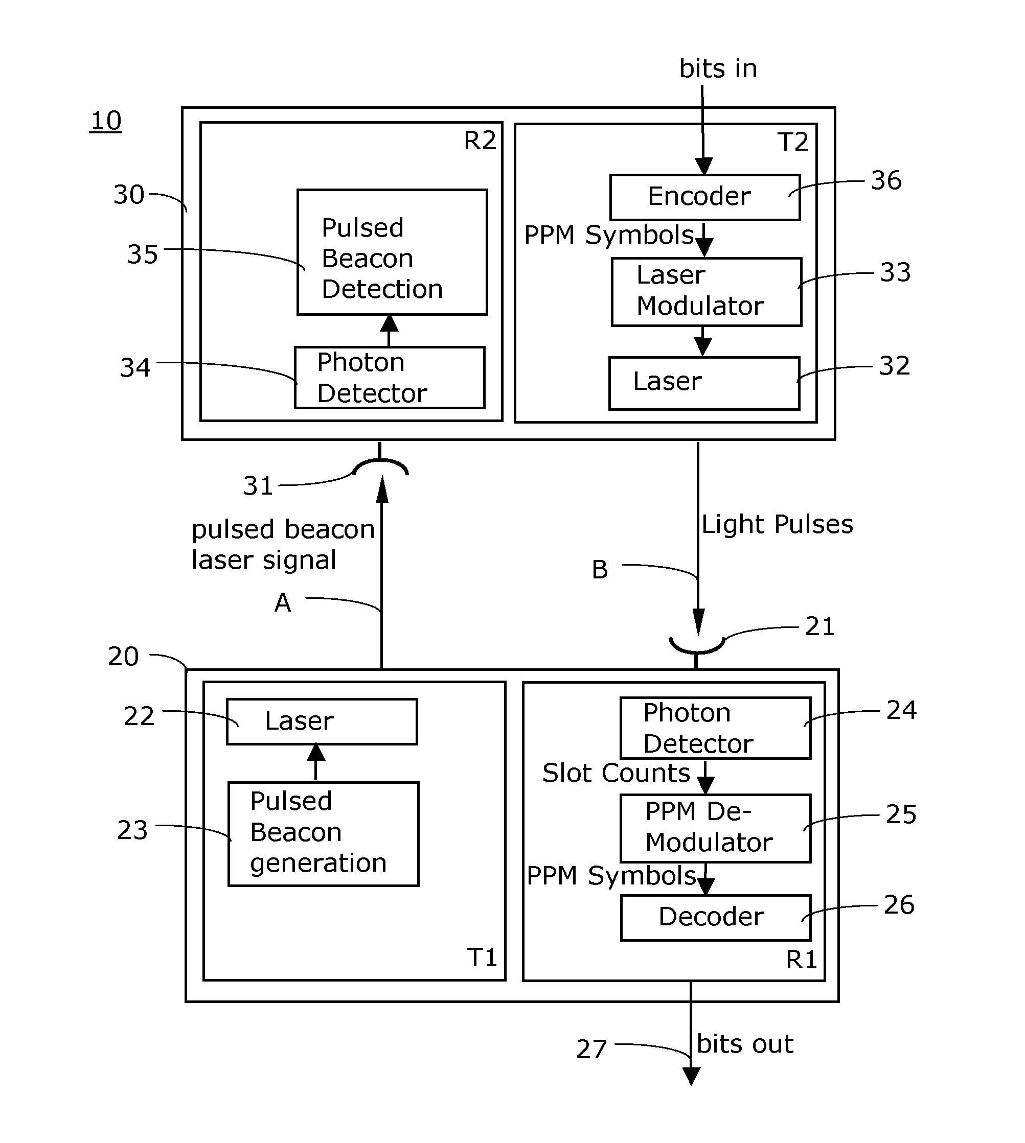
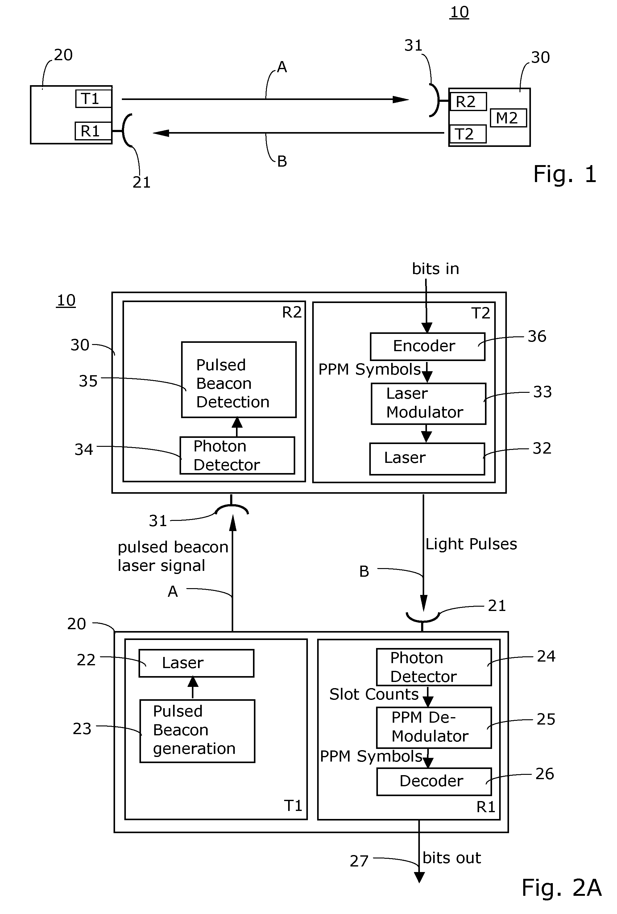
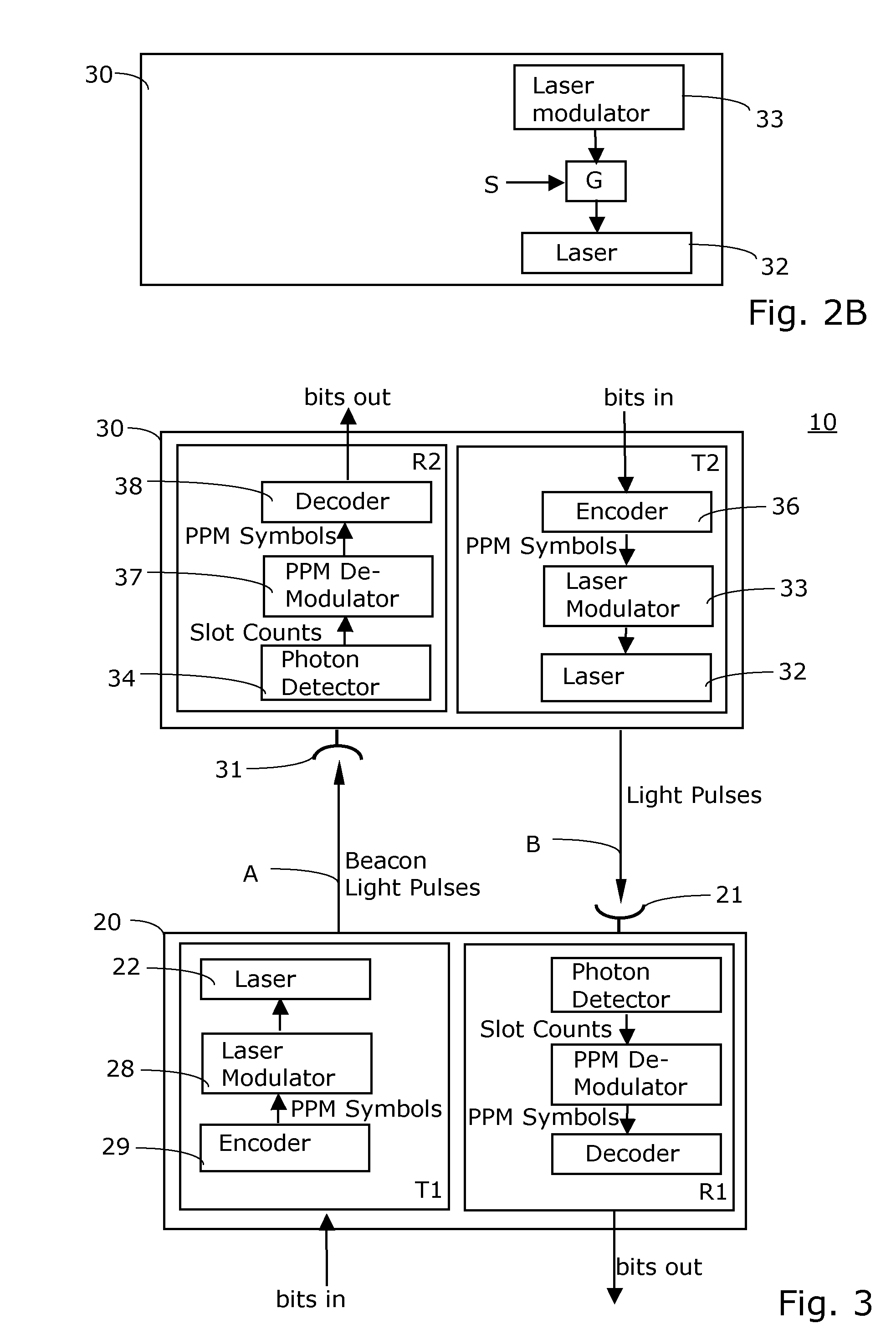
[0038]The same reference numbers are used throughout the present text for identical and similar elements or features, but also for functionally similar elements or features of the invention.

[0039]When referring in the present context to optical channels, then unguided channels are meant. A channel is a link or connection. The expressions uplink and downlink, as well as the words first, second and so on, a...


PUM


Abstract

Bi-directional laser communications system comprising a first transceiver and a second transceiver for establishing two optical channels there between. The first transceiver comprises a first transmitter with a pulsed high-power laser source for transmitting a pulsed beacon laser signal into a first of said optical channels. The second transceiver comprises a receiver with an optical antenna for receiving said pulsed beacon laser signal, said second transceiver and / or a receiving optic of said second transceiver being adjustable so that it can be adjusted with respect to said pulsed beacon laser signal. The second transceiver further comprises a second transmitter with a laser for transmitting a high energy laser signal into a second of said optical channels, and means for a separation of said first optical channel and said second optical channel. These means prevent the high energy laser signals from being transmitted into said second optical channel whenever said pulsed beacon laser signal is expected to arrive through said first optical channel.

Description

RELATED APPLICATION DATA[0001]This patent application claims benefit of the priority of the European Patent Application No. EP 06 125 318.3 filed on the 4 Dec. 2006.BACKGROUND OF THE INVENTION[0002]1. Field of the Invention[0003]The present invention concerns a bi-directional communications system and a method for bi-directional optical communication. The system and method presented herein is very well suited for communication with a satellite in deep space, for instance.[0004]2. Related Prior Art[0005]So far mainly radio frequency (RF) links are used in order to provide for a communication between a ground station and a terminal carried by a satellite in deep space. In such communications systems typically one terminal is attached to the satellite whereas another terminal is either a ground based terminal or a terminal carried aboard of a second satellite in an orbit closer to the earth.[0006]Various researchers and developers, however, are currently developing optical links to sup...

Claims


Application Information

Patent Timeline
Patent Type & Authority Patents(United States)
IPC IPC(8): H04B10/00H04B10/118
CPCH04B10/118H04L5/1469H04L25/4902H03L7/08
Inventor DREISCHER, THOMASTUCHLER, MICHAEL
Owner OERLIKON SPACE
Why Eureka
Try Eureka