
Method of estimating a degree of contamination of a front screen of an optical detection apparatus and optical detection apparatus

a technology of optical detection apparatus and front screen, which is applied in the direction of measurement devices, instruments, scientific instruments, etc., can solve the problems of only being able to determine the degree of contamination of the front screen with limited accuracy, exist contamination of the front screen, and being detected with limited reliability, so as to reduce effort, reliable and accurate, the effect of high reliability and accuracy

Active Publication Date: 2014-02-04
SICK AG
View PDF5 Cites 1 Cited by
  • Summary
  • Abstract
  • Description
  • Claims
  • Application Information

AI Technical Summary

Benefits of technology

The invention provides a method to accurately estimate the degree of contamination on the front screen of an optical detection apparatus with minimal effort and reduced construction space. This is possible because the contamination change on the front screen is insignificant between adjacent transmission radiation pulses. By evaluating the amplitude and peak shape of the averaged reception signal, a reliable and accurate estimate of the contamination can be achieved with high accuracy and reliability. This method does not require additional LEDs or a separate photo-receiver, saving construction space and energy consumption. Additionally, the method allows for the use of small components, resulting in a smaller optical detection apparatus with reliable front screen monitoring. A sufficient temporal resolution can be ensured by generating at least 50 sampled values of the reception signal in the front screen time interval to accurately evaluate the front screen peak.

Problems solved by technology

Due to noise effects and further interference effects present in the reception signal, an existing contamination of the front screen can in this respect only be detected with a limited reliability and the degree of contamination of the front screen can only be determined with limited accuracy.
This results in a front screen in the form of a frustoconical jacket, with this form producing an additional space requirement.

Method used


Image

  • Method of estimating a degree of contamination of a front screen of an optical detection apparatus and optical detection apparatus
  • Method of estimating a degree of contamination of a front screen of an optical detection apparatus and optical detection apparatus
  • Method of estimating a degree of contamination of a front screen of an optical detection apparatus and optical detection apparatus

Examples


Embodiment Construction

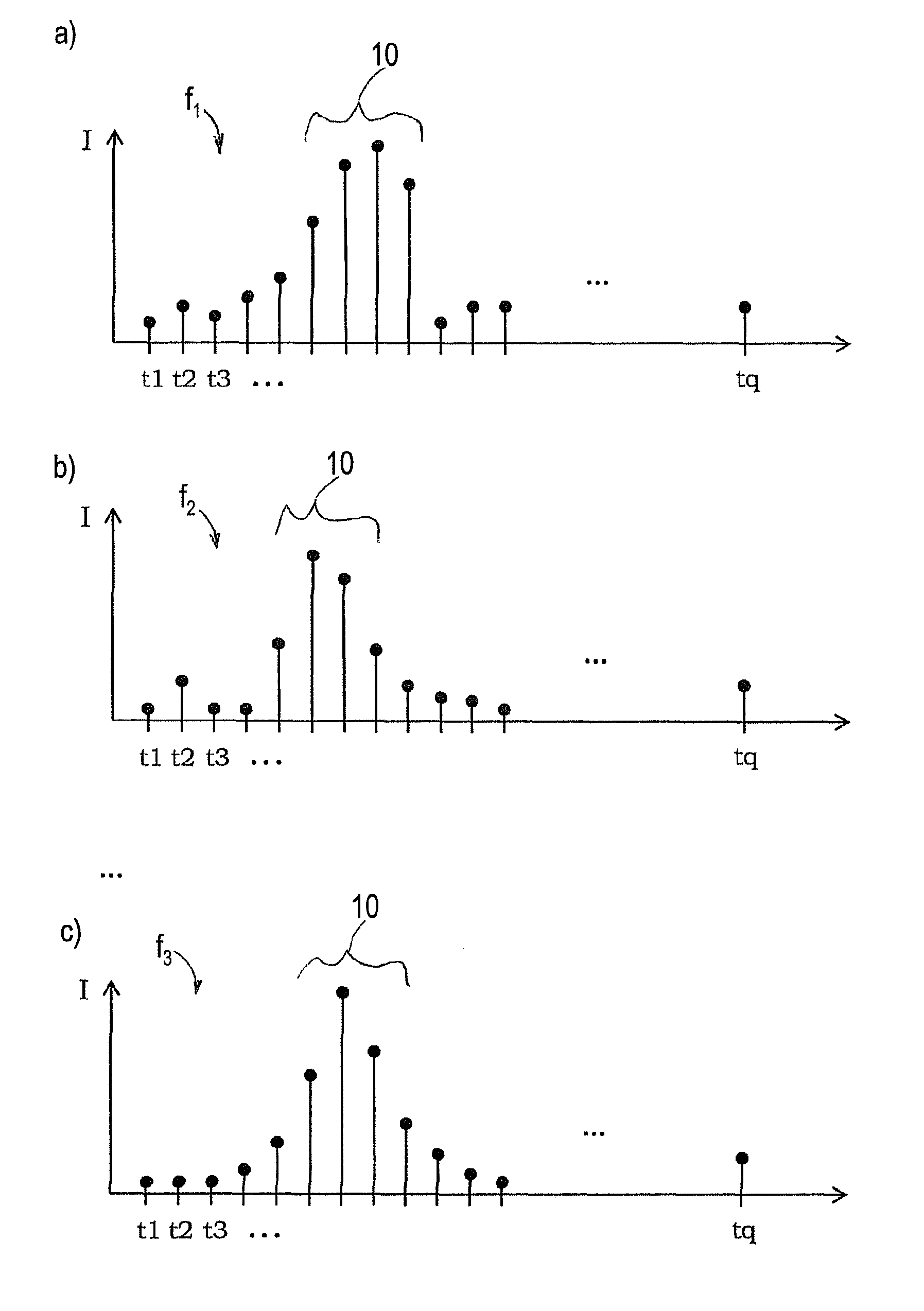
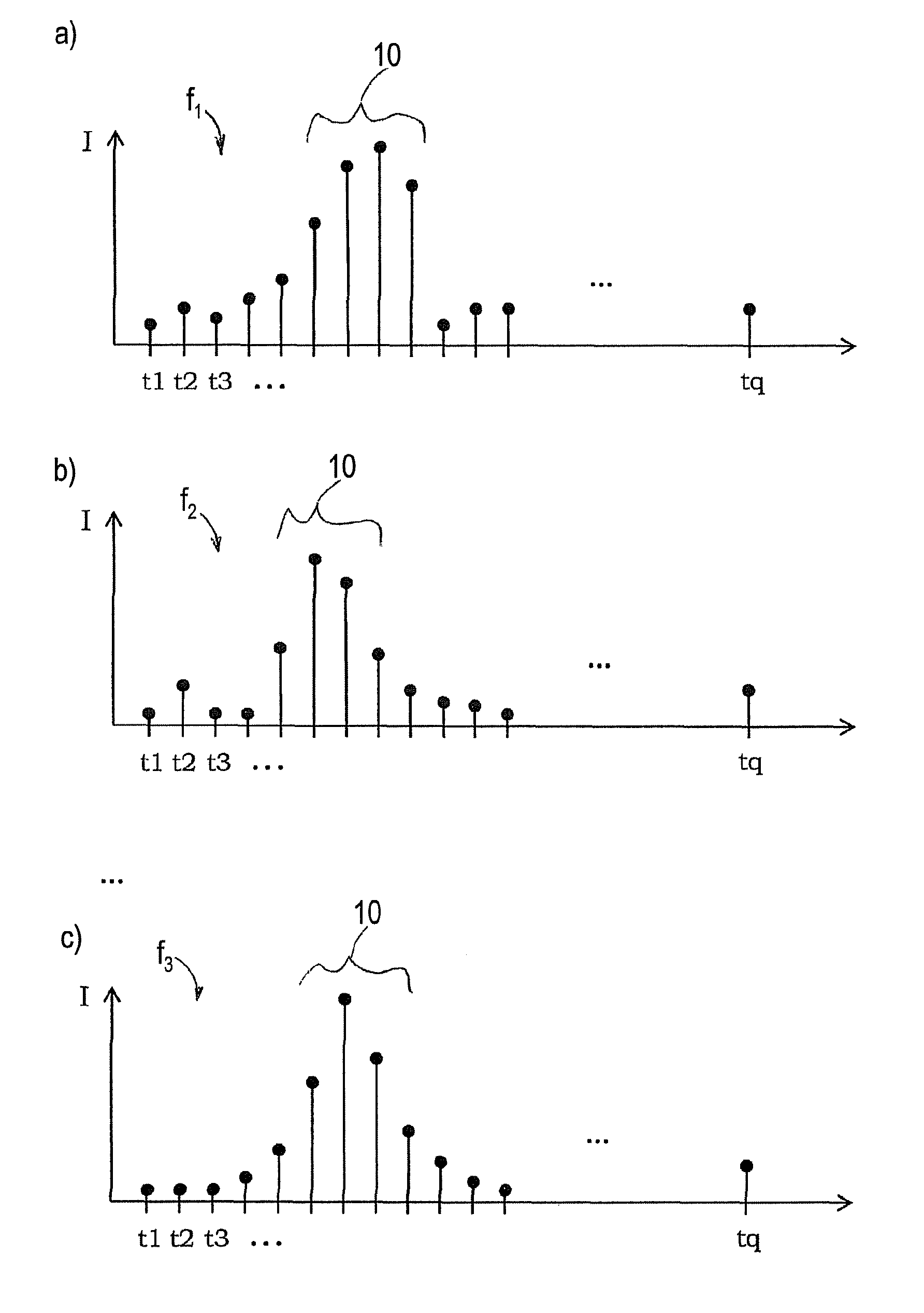
[0043]FIG. 1a shows a first reception signal (f1) which has been generated from a transmission radiation pulse and which includes a plurality of q sampled values f1(t1) to f1(tq), wherein a sampled value f1(tj), j=1 . . . q respectively indicates the intensity I of the received back radiation of the transmission radiation pulse at a point in time tj at a predefined time interval from the transmission of the transmission radiation pulse (t=0). Only some sampled values f1(tj) are shown as representatives in FIG. 1a. In reality, the number q of sampled values fi(tj), j=1 . . . q per reception signal fi, i=1 . . . p can be substantially larger. FIG. 1b shows a second reception signal f2 which was generated from a second transmission radiation pulse transmitted following the first transmission radiation pulse.

[0044]The reception signals f1 and f2 shown in FIGS. 1a and 1b are representative for a plurality of reception signals fi, i=1 . . . p which belong to transmission radiation pulses ...


PUM

PropertyMeasurementUnit
scan angleaaaaaaaaaa
timeaaaaaaaaaa
timeaaaaaaaaaa

Abstract

A method for estimating a degree of contamination of a front screen of an optical detection apparatus is provided comprising the steps: Transmitting a plurality (p) of transmission radiation pulses into a detection zone; generating a reception signal for each transmission radiation pulse including a plurality (q) of sampled values, a sampled value indicating the intensity of the received back radiation of the transmission pulse after a predefined time interval from the transmission of the transmission radiation pulse; generating an averaged reception signal having a plurality (q) of sampled values from the plurality of reception signals, with those respective sampled values of the reception signals being added which were determined at mutually corresponding points in time to determine a sampled value of the averaged reception signal; generating at least one front screen contamination value by evaluating an amplitude value and / or a measured peak shape value of the averaged signal.

Description

BACKGROUND[0001]1. Technical Field[0002]The present invention relates to a method of estimating a degree of contamination of a front screen of an optical detection apparatus which includes the transmission of a plurality of transmission radiation pulses into a detection zone as well as the generation of a reception signal for each transmission radiation pulse, wherein the reception signal has a plurality of sampled values and a sampled value respectively indicates the intensity of the received back radiation of the respective transmission radiation pulse at a point in time at a predefined time interval from the transmission of the transmission radiation pulse. The invention additionally relates to a corresponding optical detection apparatus.[0003]2. Related Art[0004]An optical detection apparatus, e.g. a laser scanner, usually has a front screen which is arranged in the beam path between a transmission unit of the optical detection unit and the environment to be detected.[0005]EP 2 ...

Claims


Application Information

Patent Timeline
Patent Type & Authority Patents(United States)
IPC IPC(8): G01N21/00G01S17/87G01S17/89
CPCG01S17/87G01S7/483G01S17/89
Inventor HULM, CHRISTIANMOHRLE, MANUEL
Owner SICK AG
Learn More