
Shaft furnace direct reduction device and discharging method thereof

A shaft furnace, direct technology, applied in the field of shaft furnace direct reduction device and its discharge, can solve the problems of affecting product quality, easy damage to the furnace wall, increased force on the side wall, etc., to increase structural stability and firmness , does not affect the operation rate, and reduces the construction cost

Active Publication Date: 2020-11-10
唐山中科乾海环保科技有限公司 +1
View PDF11 Cites 0 Cited by
  • Summary
  • Abstract
  • Description
  • Claims
  • Application Information

AI Technical Summary

Problems solved by technology

The shaft furnace has the following disadvantages: (1) The temperature near the burner is high, and the temperature away from the burner is low, resulting in uneven temperature of the charge, affecting product quality, and affecting the reduction effect; (2) Rectangular vertical reduction reaction There are no reinforcing ribs on the outer walls on both sides of the chamber. When the furnace material reacts at high temperature, the side walls will be stressed and the furnace wall will be easily damaged. (3) The heat exchange method is used to recover part of the heat of the hot flue gas, and the heat exchange efficiency is low.
This patent has the following disadvantages: (1) the structure is quite complicated, the construction is difficult, the amount of refractory materials is large, and the overall investment is high; (2) the temperature distribution of the air supply channel is uneven, which affects the product quality and the reduction effect; (3) the thermal There is no effective reinforcement treatment for the exchange surface wall. When the furnace material reacts at high temperature, the force on the side wall will increase, and the heat exchange surface wall will be easily damaged.
According to the description of the patent, its disadvantages are: (1) the bottom discharge of the shaft furnace needs to adopt a frame structure, which greatly increases the construction investment; (2) a single reduction chamber needs to be equipped with multiple discharge units, which increases the investment; (3) each row The structure of the material unit is quite complex, with many systems, many equipment, many mechanical actions, many accidents, and low operation rate; (4) The thermal discharge equipment works continuously in a high temperature environment, resulting in large losses, short life, low operation rate, and cannot be maintained

Method used


Image

  • Shaft furnace direct reduction device and discharging method thereof
  • Shaft furnace direct reduction device and discharging method thereof
  • Shaft furnace direct reduction device and discharging method thereof

Examples


Embodiment 1

[0066] see Figure 4 to Figure 11 , the hollow sleeve is a hollow cylinder 15 structure, the front end of the hollow cylinder 15 is provided with convex teeth 16, the rear end of the hollow cylinder 15 is fixedly connected with the front end of the hollow square cylinder 17 through a flange, and the inner chambers at both ends of the hollow square cylinder 17 are arranged There is a chute 18, and the outer wall of the hollow square tube 17 is provided with hemp teeth 19, and the hemp teeth 19 are used to cooperate with the driving device, and the driving device adopts a hydraulic oil cylinder. The lower part of the outer surface of the hollow cylinder 15 and the hollow square cylinder 17 is slidingly connected with the first positioning slideway 20, and the first positioning slideway 20 is fixed on the first frame body 21; the main body of the first positioning slideway 20 is a groove structure, The front end of the first positioning slideway 20 is an arc-shaped structure matc...

Embodiment 3

[0072] see Figure 18 and Figure 19 , the rod body of the discharge device is composed of a solid square rod head 46 at the front end and a first hollow square rod 47 at the rear end, etc., the rear end of the first hollow square rod 47 is fixedly connected with the front end of the second hollow square rod 48 through a flange, The outer wall of the second hollow square rod 48 is provided with hemp teeth 19, and the hemp teeth 19 are used to cooperate with the hydraulic cylinder. The lower part of the outer surface of the hollow square rod is slidingly connected with the fourth positioning slideway 50, and the fourth positioning slideway 50 is fixed on the third frame body 49; the fourth positioning slideway 50 is a groove structure. The second hollow square rod 48 is connected with the second main hydraulic cylinder 51 through hemp teeth 19, the cylinder core of the second auxiliary hydraulic cylinder 52 is connected with the cylinder wall of the second main hydraulic cylin...


PUM


Abstract

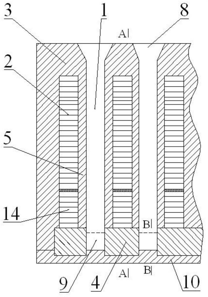
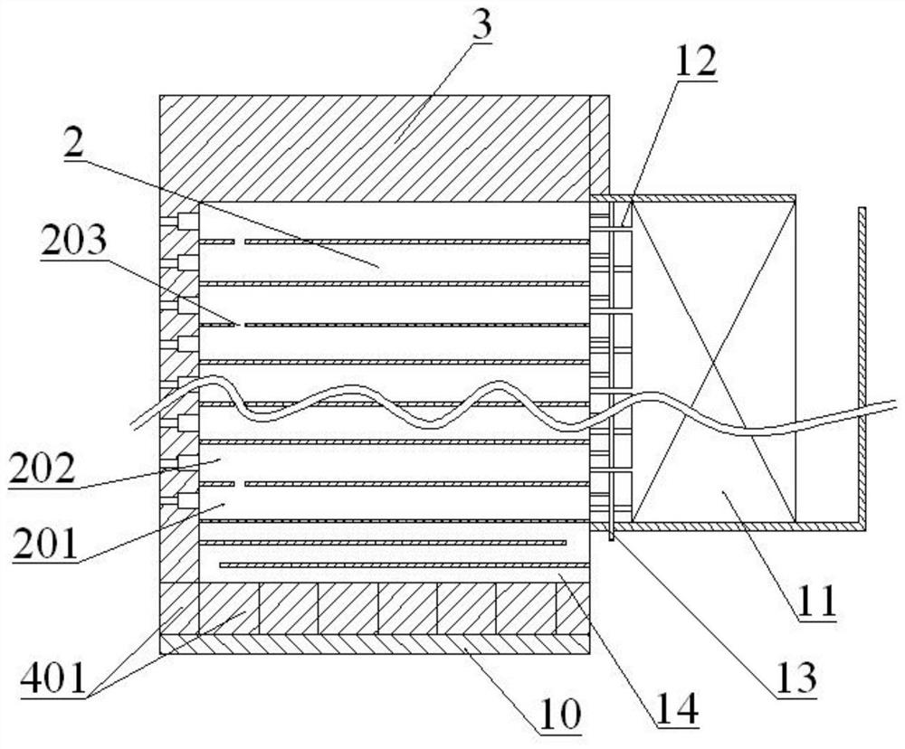
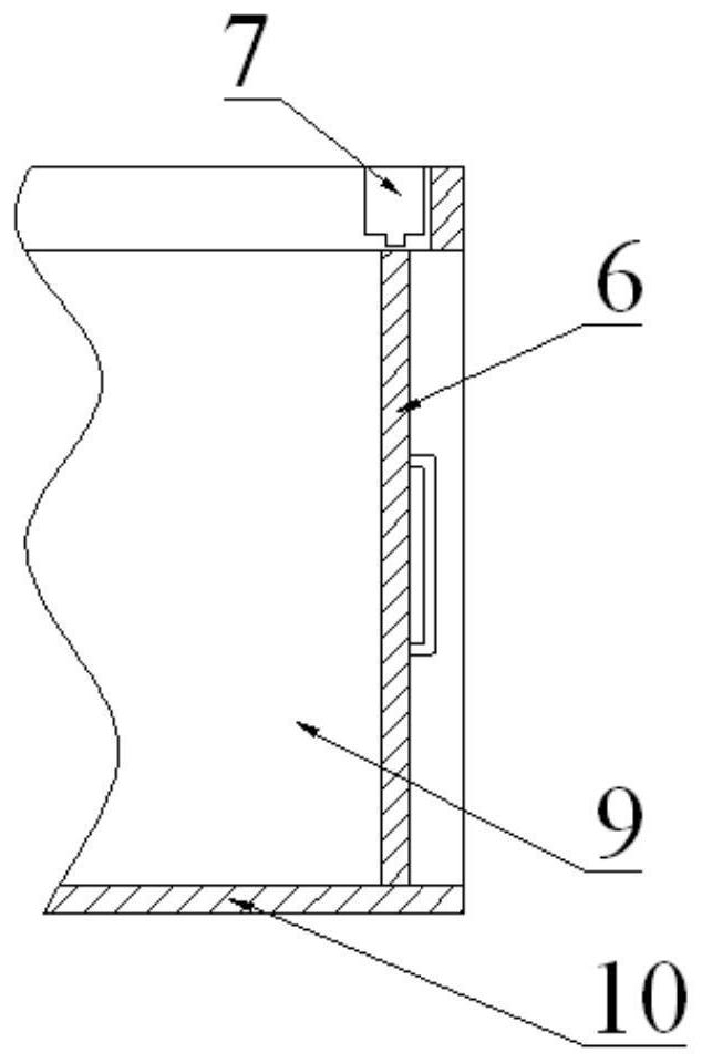
The invention discloses a shaft furnace direct reduction device and a discharging method thereof, and relates to the technical field of non-blast-furnace smelting reduction. The shaft furnace direct reduction device comprises a shaft furnace and discharging devices, and the shaft furnace comprises reaction chambers and combustion chambers; two side walls of the lower part of each reaction chamberare of a reinforced furnace wall structure, and the combustion chambers are arranged above the reinforced furnace wall structures; discharge ports are respectively formed in the bottoms of the other two side surfaces of each reaction chamber, and the upper edges of the discharge ports are not higher than the upper edges of reinforced furnace walls; and the discharging devices are arranged on the outer side of each discharging port in one end and comprise supporting pieces and discharging pieces, one ends of the supporting pieces and one ends of the discharging pieces are connected with drivingdevices, and the interiors or the bottoms of the supporting pieces are in sliding fit with the discharging pieces. According to the device, the structure that the discharging ports are formed in thetwo sides of the shaft furnace is adopted, the construction cost is greatly reduced, and the structural stability and firmness are improved; and the discharging devices work intermittently, and are used for discharging of a plurality of different reaction chambers or a single reaction chamber, the discharging devices are few, investment is low, equipment maintenance is facilitated, and the operation rate is not affected.

Description

technical field [0001] The invention relates to the technical field of non-blast furnace smelting reduction, in particular to a shaft furnace direct reduction device and a discharge method thereof. Background technique [0002] At present, the main processes of direct reduction include: gas-based shaft furnace process, coal-based rotary kiln process, rotary hearth furnace process, tunnel kiln process and coal-based shaft furnace process. Among them, the coal-based shaft furnace process is suitable for China's current situation where coal is the main energy source, and has the most potential for development. However, there are some deficiencies in the existing coal-based shaft furnace technology, which are mainly reflected in: (1) The overall furnace adopts a frame structure and a lower discharge method, resulting in an increase in design standards, material standards, construction standards, and increased material consumption. High construction investment; (2) A single reac...

Claims


Application Information

Patent Timeline
Patent Type & Authority Applications(China)
IPC IPC(8): C21B13/02F27B1/21F27B1/12F27B1/24
CPCC21B13/02F27B1/21F27B1/12F27B1/24
Inventor 张春雷
Owner 唐山中科乾海环保科技有限公司
Learn More