Auto trimming oscillator

a technology of auto trimming and oscillator, which is applied in the direction of automatic control, electrical equipment, etc., can solve problems such as difficult to find a solution, and achieve the effects of low cost fabrication, small area, and fast and accurate determination of oscillator trimming values

Inactive Publication Date: 2011-08-09
ATMEL CORP
View PDF7 Cites 5 Cited by
  • Summary
  • Abstract
  • Description
  • Claims
  • Application Information

AI Technical Summary

Benefits of technology

[0006]Some advantages of the disclosed auto trimming oscillator include but are not limited to: fast and accurate determination of oscillator trimm

Problems solved by technology

Even using other RC oscillator topologies (e.g., charging and discharging an internal capacitor with controlled

Method used


Image

  • Auto trimming oscillator
  • Auto trimming oscillator
  • Auto trimming oscillator

Examples


example trimming sequence

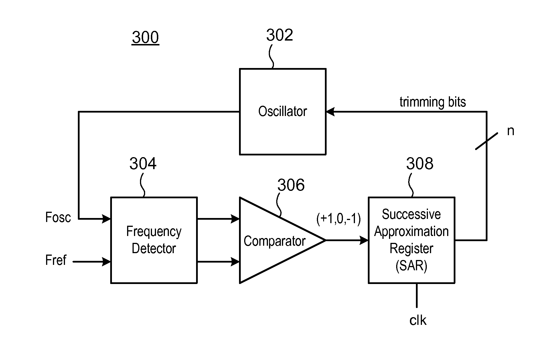
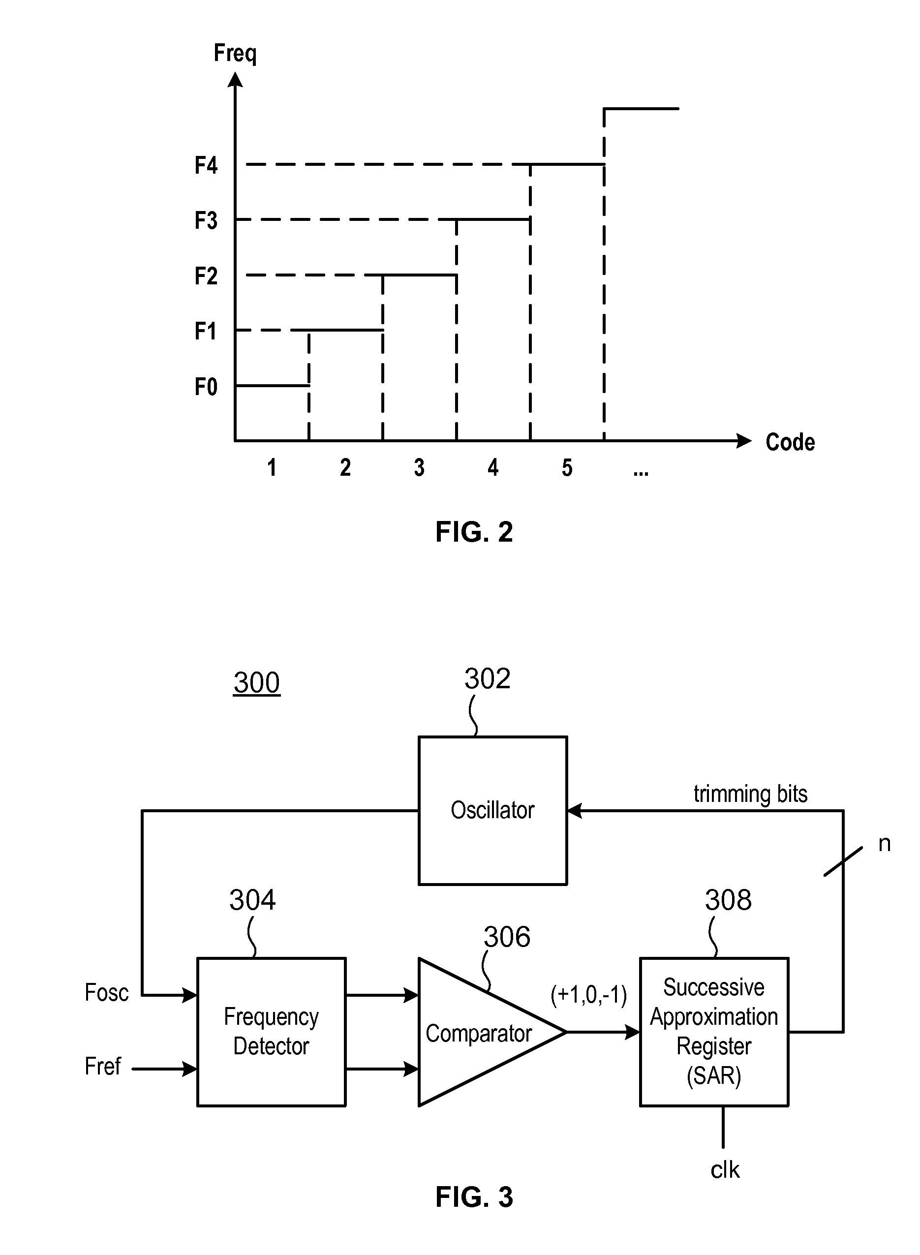
[0021]FIG. 4 includes graphs illustrating the example trimming sequence shown in Table I. In this example, the auto trimming oscillator 300 shown in FIG. 3 has been synthesized using a 0.15 um CMOS process. The reference frequency (Fref) is 4 MHz and the SAR 308 provides 7 trimming bits (e.g., 7-bit digital codes).

[0022]Graphs “a” and “b” illustrate an example trimming sequence for providing the digital code necessary for the oscillator 302 to compensate for process variation. More particularly, graph “a” represents the frequency of the oscillator 302 versus time and Graph “b” is a digital bit (also referred to as the “eot signal”) that controls the overall trimming sequence duration. Graph “a” shows a 7 step trimming sequence where the reference frequency is about 4 MHz and the oscillator frequency is about 3.5 MHz. The auto trimming sequence starts when the eot signal (Graph “b”) goes low.

[0023]At step 0, Fosc is initialized by a trimming code representing a midrange value of the ...


PUM


Abstract

An auto trimming oscillator includes a Successive Approximation Register (SAR), a frequency detector and an n-bit comparator. The SAR is used to iteratively trim the oscillator output clock frequency based on a difference between a reference clock frequency and the oscillator output clock frequency. The oscillator is trimmed to deliver a clock frequency which is a closest match to the reference clock frequency.

Description

TECHNICAL FIELD[0001]This subject matter relates generally to electronic circuits, and more particularly to trimming oscillator circuits.BACKGROUND[0002]Many modern electronic circuits (e.g., microcontrollers) use internal CMOS oscillators to generate clocks. In many applications, a low variation CMOS oscillator is needed. Conventional CMOS oscillators are manually trimmed by test engineers with dedicated, external tester resources. Some CMOS oscillators use a resistive-capacitive (RC) structure.[0003]A conventional RC oscillator with a Schmitt trigger is shown in FIG. 1A. The RC oscillator 100 includes a capacitor 102 (C), a Schmitt trigger 104 (11) and a resistor 106 (R). The output clock 108 has a frequency that is directly proportional to the RC product. A typical integrated poly-silicon resistor can provide a relative frequency variation of about + / −25% and a typical integrated CMOS capacitor can provide a relative frequency variation of about + / −15%. In this case, the overall ...

Claims


Application Information

Patent Timeline
IPC IPC(8): H03L7/085
CPCH03L7/085H03L7/089H03L7/0991
Inventor FIEVET, SEBASTIENCUENCA, MICHEL
Owner ATMEL CORP
Why Eureka
Try Eureka