System and method for installation of decorative molding

a technology of decorative molding and installation method, which is applied in the direction of covering/lining, construction, building components, etc., can solve the problems of affecting the appearance of the molding, the usual method of attaching crown molding to the wall and ceiling does not work, and the time and complexity of the process are added, so as to prevent the molding assembly from sagging and increase the rigidity

Active Publication Date: 2011-08-16
MACMILLAN ROBERT +1
View PDF17 Cites 20 Cited by
  • Summary
  • Abstract
  • Description
  • Claims
  • Application Information

AI Technical Summary

Benefits of technology

[0016]The present invention can also be used in an existing interior space without a suspended ceiling and with a standard fixed ceiling. Here the molding assembly has a lower attachment point, and no upper attachment point. The vertical mounting surface of the molding assembly does not extend above the height of the decorative face (and may be slightly below). The lower channel exists in this example, but not to accommodate a wall panel. The vertical mounting surface extends below the decorative face of the molding assembly and provides an attachment point. A vertical channel will run the length of the molding inside the bottom edge of the decorative face. This channel will likely be thinner, as more material will be needed on the flange to strengthen and provid

Problems solved by technology

The timing may be undesirable as there are usually many different types of finishing work that must be coordinated at the same time.
Since the suspended ceiling is not structural, the usual method of attaching crown molding to the wall and ceiling does not work.
This method adds time and complexity to the process, as well as cost.
Installing crown molding can prove a difficult task for a nonprofessional installer.
A preferred method for installing corner joints is accomplished by scribing the profile of the adjoining surfaces and coping the proper angle—a difficult task for an inexperienced installer.
This method, however, still requires that the walls are built and finishe

Method used


Image

  • System and method for installation of decorative molding
  • System and method for installation of decorative molding
  • System and method for installation of decorative molding

Examples


Embodiment Construction

[0024]The following detailed description is of the best mode or modes of the invention presently contemplated. Such description is not intended to be understood in a limiting sense, but to be an example of the invention presented solely for illustration thereof, and by reference to which in connection with the following description and the accompanying drawings one skilled in the art may be advised of the advantages and construction of the invention. Reference will now be made in detail to the preferred implementation of the present invention as illustrated in the accompanying drawings. Wherever possible, the same reference numbers will be used throughout the drawings and the following description to refer to the same or like parts.

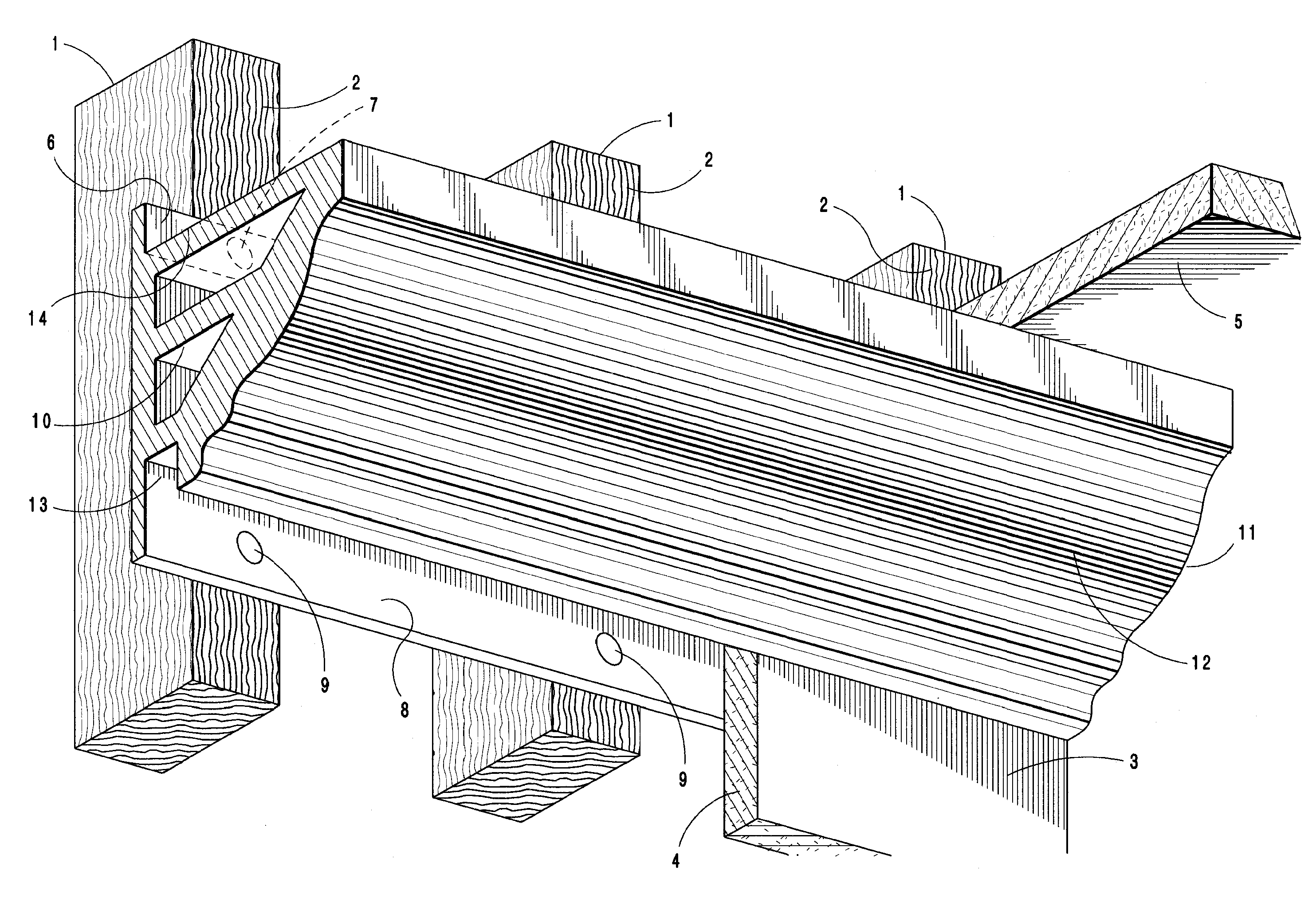
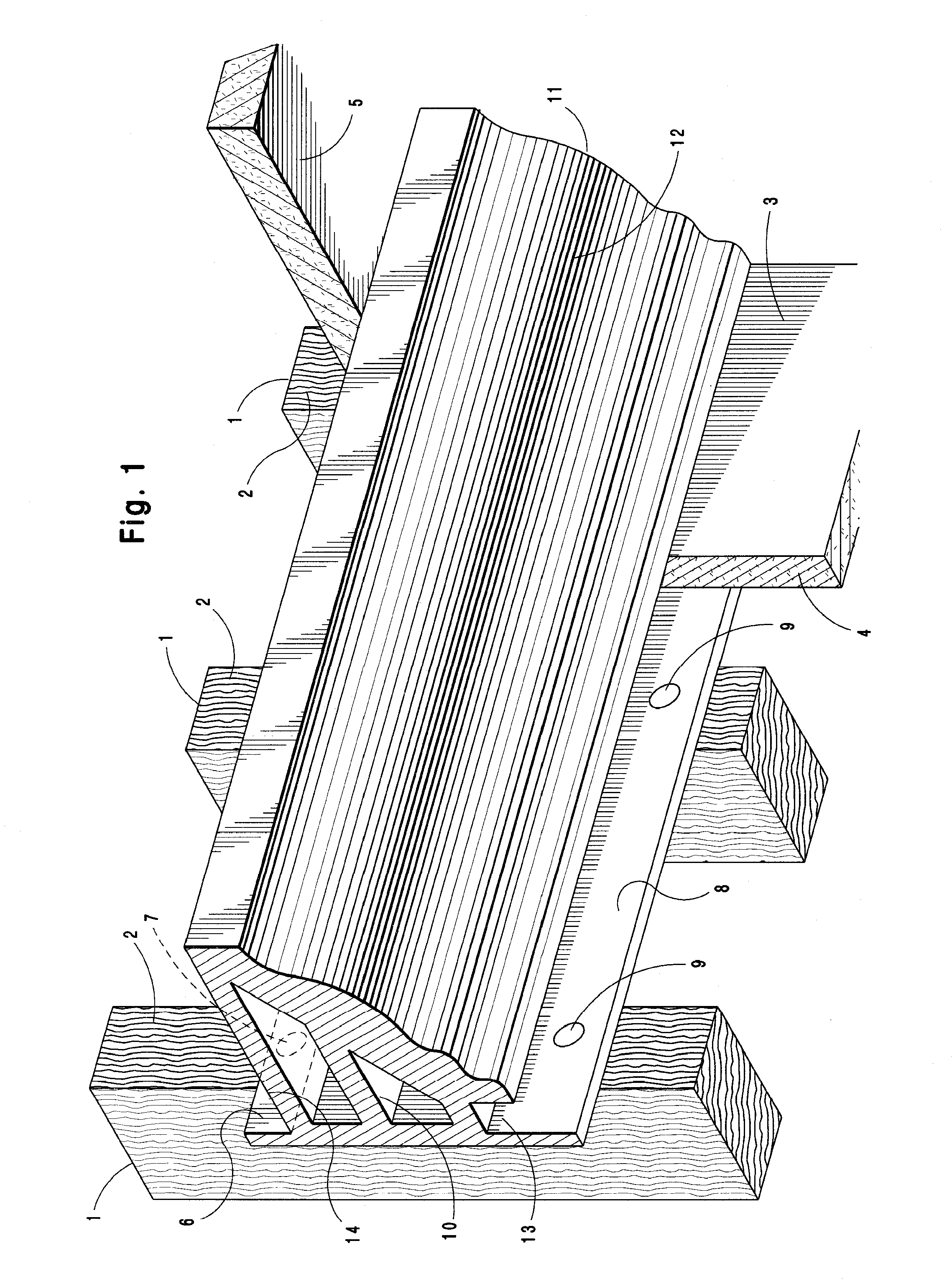
[0025]FIG. 1 provides a perspective view of a decorative molding system embodying the principles and concepts of the present invention. Reference numeral 11 designates generally the invention itself as described in this embodiment. Although the representa...


PUM


Abstract

A molding system for use in interior spaces for use either with new construction or finished spaces, and in addition can be used with either a suspended ceiling or conventional ceiling, whereby the molding is incorporated with the wall and ceiling surfaces in such a manner that the joints with the ceiling and wall are plumb and being mounted such that the decorative molding surface of the molding can be installed in a finished form that does not require further finishing after installation.

Description

CROSS REFERENCE TO RELATED APPLICATIONS[0001]This application claims the benefit of provisional applications 60 / 940,874 filed on May 30, 2007 and 60 / 976,441 filed on Sep. 30, 2007, the disclosures of which are incorporated by reference in their entiretyBACKGROUND[0002]The present invention is directed to systems and methods for installing decorative molding in a building's interior space, and more particularly to a molding assembly and method of installing molding more quickly and easily in either a new construction or finished interior space, and for installing molding in an interior space having a suspended ceiling.[0003]It is often desirable for buildings' interior spaces to have decorative trim at the top of interior walls. This is usually where the walls meet the ceiling and can be referred to as crown molding. When a building is being built, crown molding is usually installed after nearly all other construction is complete. The timing may be undesirable as there are usually ma...

Claims


Application Information

Patent Timeline
IPC IPC(8): E04C2/38E04F19/04E04F19/02
CPCE04F19/0436
Inventor MACMILLAN, ROBERTHOFFMAN, JEREMY P.
Owner MACMILLAN ROBERT
Why Eureka
Try Eureka