Anti-lock brake device for use with a brake rotor disc

a technology of anti-lock brake and rotor disc, which is applied in the direction of braking discs, braking systems, instruments, etc., can solve the problems of anti-lock brake systems, poor performance, signal failure, etc., and achieve accurate and reliable readings

Active Publication Date: 2011-08-16
PERFORMANCE FRICTION
View PDF19 Cites 18 Cited by
  • Summary
  • Abstract
  • Description
  • Claims
  • Application Information

AI Technical Summary

Benefits of technology

[0013]An aspect of the invention provides a brake assembly having a rotor with an ABS tone ring for use with an anti-lock brake assembly that provides accurate and reliable readings.
[0014]Another aspect of the invention provides a brake assembly having a rotor with an ABS tone ring for use with an anti-lock brake assembly that has a relatively long service life.
[0015]An additional aspect of the invention provides a brake assembly having a rotor with an ABS tone ring for use with an anti-lock brake assembly that accommodates more versatile and durable coatings suitable for high temperature environments at a reasonable cost.

Problems solved by technology

Inadequate magnetic signal strength or incorrect geometric shape may cause signal failure, which can be further influenced by rotating velocity.
Problems have arisen with anti-lock brake systems in terms of poor performance due to irregularities and corrosion of the teeth.
The coating is intended to lengthen the shelf life of the rotor and impede corrosion.
These dual property constraints limit the possible types of coatings suitable for this application.
However, coatings suitable for rotor application degrade at high temperatures.
When the coating breaks down, the teeth can corrode.
Corrosion alters the geometry of the teeth and causes inaccurate readings from the anti-lock braking sensor.
This significantly shortens the useful life of the brake rotor assembly.
When the sensor generates inaccurate readings, the assembly requires repair or replacement.
A problem also exists due to the state of the art casting methods and tolerances, which exist in casting of the teeth.
Cast teeth will not be sufficiently accurate for most applications, and the inaccuracy in geometry will cause signal failure at higher velocities.
To further machine the teeth for accuracy adds significant additional cost.
Another problem with cast iron tone rings relates to the magnetic properties of cast iron and how the properties change with temperature.

Method used


Image

  • Anti-lock brake device for use with a brake rotor disc
  • Anti-lock brake device for use with a brake rotor disc
  • Anti-lock brake device for use with a brake rotor disc

Examples


Embodiment Construction

[0035]The disc brake rotor assembly described herein is preferred for use on vehicles, including automobiles, racing vehicles, trucks, heavy duty trucks, motorcycles and the like. The vehicles particularly suitable for use with this invention can include those vehicles having a gross vehicle weight of about 10,000 pounds and above, especially delivery trucks and buses. However, the inventive concepts discussed herein can be used in any type of application that uses rotary brakes, including automotive, other types of motorized vehicles, or railcars. The invention is especially applicable for retrofitting in existing vehicles.

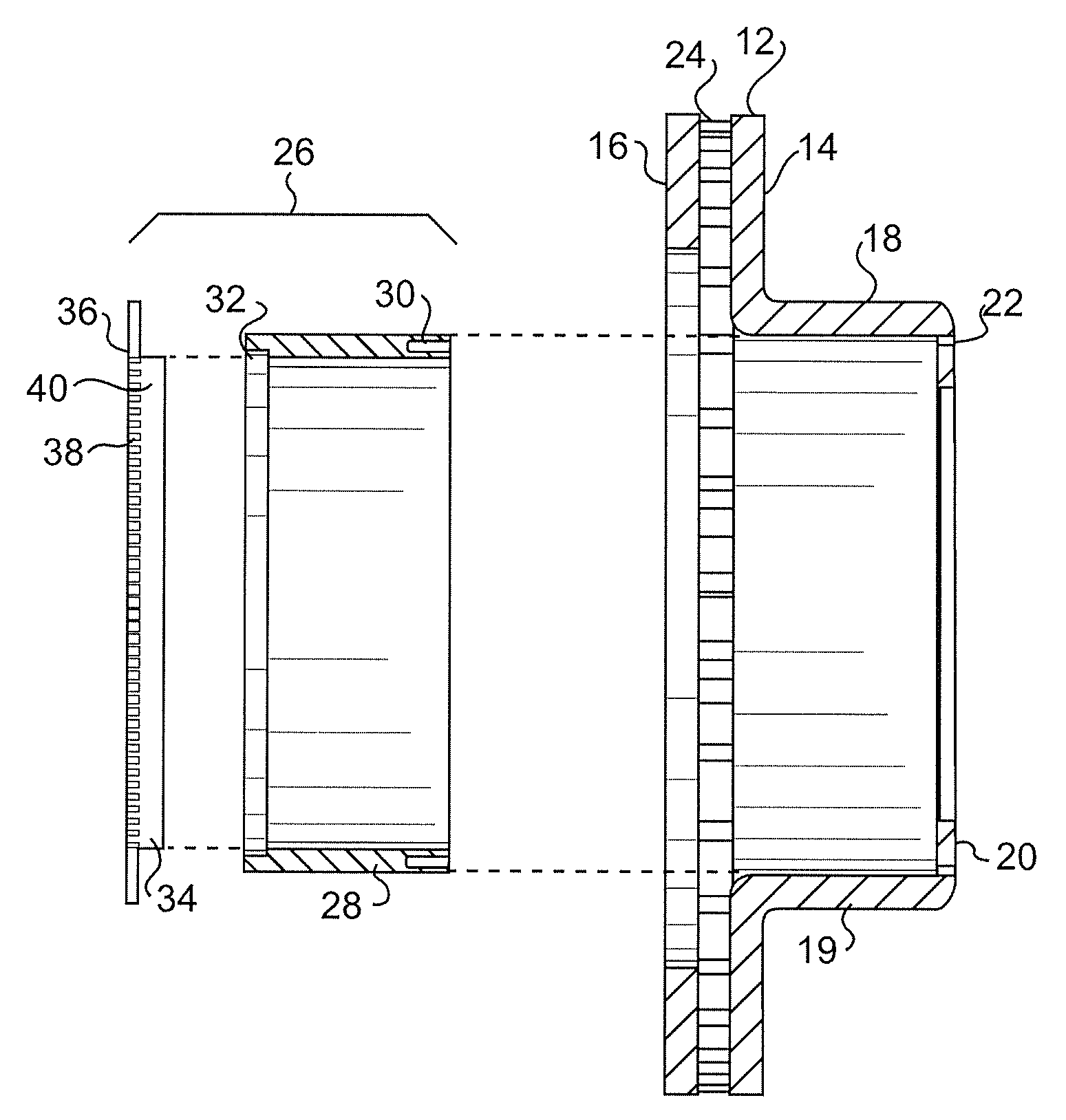
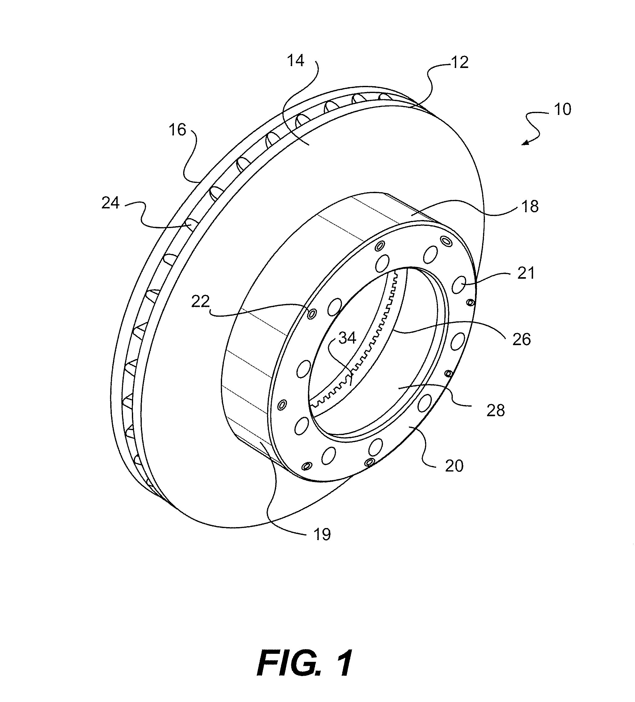
[0036]FIG. 1 shows a brake rotor disc assembly 10 in accordance with the invention. The brake rotor disc assembly 10 includes a rotor disc 12 having a pair of opposed braking plates 14, 16 with friction material on the surface of each plate and a hat portion 18 for connection to a wheel hub (not shown) as is known. The hat portion 18 is defined by a cylindrical b...


PUM

PropertyMeasurementUnit
weightaaaaaaaaaa
temperaturesaaaaaaaaaa
weightaaaaaaaaaa

Abstract

A disc brake assembly includes a rotor with an ABS tone ring insert assembly that functions as a rotation indicator in an anti-lock braking system. The insert is positioned in the hat of a rotor disc in a spaced relationship and is mounted to the mounting flange of the rotor disc. Forming the ring insert separately from the rotor disc also allows different coating materials to be used on the tone ring that may be more heat resistant. The ring insert assembly can be made of powder metal or made as a cast iron cylinder with a toothed cap made of powder metal having a corrosion resistant coating. Cost savings can be realized along with high performance when only a portion of the assembly if made of powder metal and coated.

Description

BACKGROUND OF THE INVENTION[0001]1. Field of the Invention[0002]The invention relates to brake assemblies, especially vehicular brakes including brake rotors attached to wheel hubs. This invention particularly relates to brake rotor disc assemblies equipped with anti-lock brake devices.[0003]2. Description of Related Art[0004]Typically, vehicles are equipped with a brake system to provide controlled slowing or stopping of the wheels to halt movement of the vehicle. A common type of brake system is a disc brake assembly associated with the wheels that is actuated by hydraulic or pneumatic pressure generated by an operator of the vehicle depressing a foot pedal. As is known, a disc brake assembly generally includes a rotor secured to the wheel of the vehicle for rotation therewith. The rotor has a pair of opposed friction plates that are selectively engaged by brake shoes supported on opposite sides of the rotor for sliding movement relative thereto.[0005]In operation, the brake pads,...

Claims


Application Information

Patent Timeline
Patent Type & Authority Patents(United States)
IPC IPC(8): F16D65/10
CPCB60T8/329F16D65/12F16D66/00G01P3/488Y10T29/49826F16D2066/003F16D2065/1392
Inventor BURGOON, DONALD L.DALTON, JOSEPH BRADLEYPAUL, SCOTT ANDREWVAN HARKEN, CRAIG A.
Owner PERFORMANCE FRICTION
Why Eureka
Try Eureka