
Vibration damper

a vibration damper and damper technology, applied in the field of vibration dampers, can solve the problems of limited regulation quality and limited quality, and achieve the effect of improving quality and reducing the effect of vibration

Inactive Publication Date: 2011-08-16
HITACHI AUTOMOTIVE SYST EURO GMBH
View PDF72 Cites 13 Cited by
  • Summary
  • Abstract
  • Description
  • Claims
  • Application Information

AI Technical Summary

Benefits of technology

[0004]Therefore it is the underlying object of the invention to improve a vibration damper of the above mentioned type in such a manner so that therewith different damper forces for the extension or retraction springing or spring travel are exactly regulatable in a simple manner.
[0006]The invention has the advantage that with such vibration dampers large differences of the damper forces during the extension and retraction springing or spring travel can be regulated-out in common very quickly. In that regard, by the selection of the gap intersection or gating point, advantageously the relationship or ratio of the damper forces can be changed, without impairing the regulation quality.

Problems solved by technology

If regulated hydraulic or pneumatic dampers with a characteristic field are utilized for that purpose, then the regulation quality is, however, limited with such a force relationship.
Because the two non-return check valves are oriented contrary to one another and are embodied the same in both throttle paths, the result is that always the same throughflow quantity arises in both throughflow directions, so that also with such a vibration damper the damping regulation of different damper forces for retraction and extension springing or spring travel requires a large regulation spread or range, whereby also in this case the regulation quality is limited.

Method used


Image

  • Vibration damper
  • Vibration damper
  • Vibration damper

Examples


Embodiment Construction

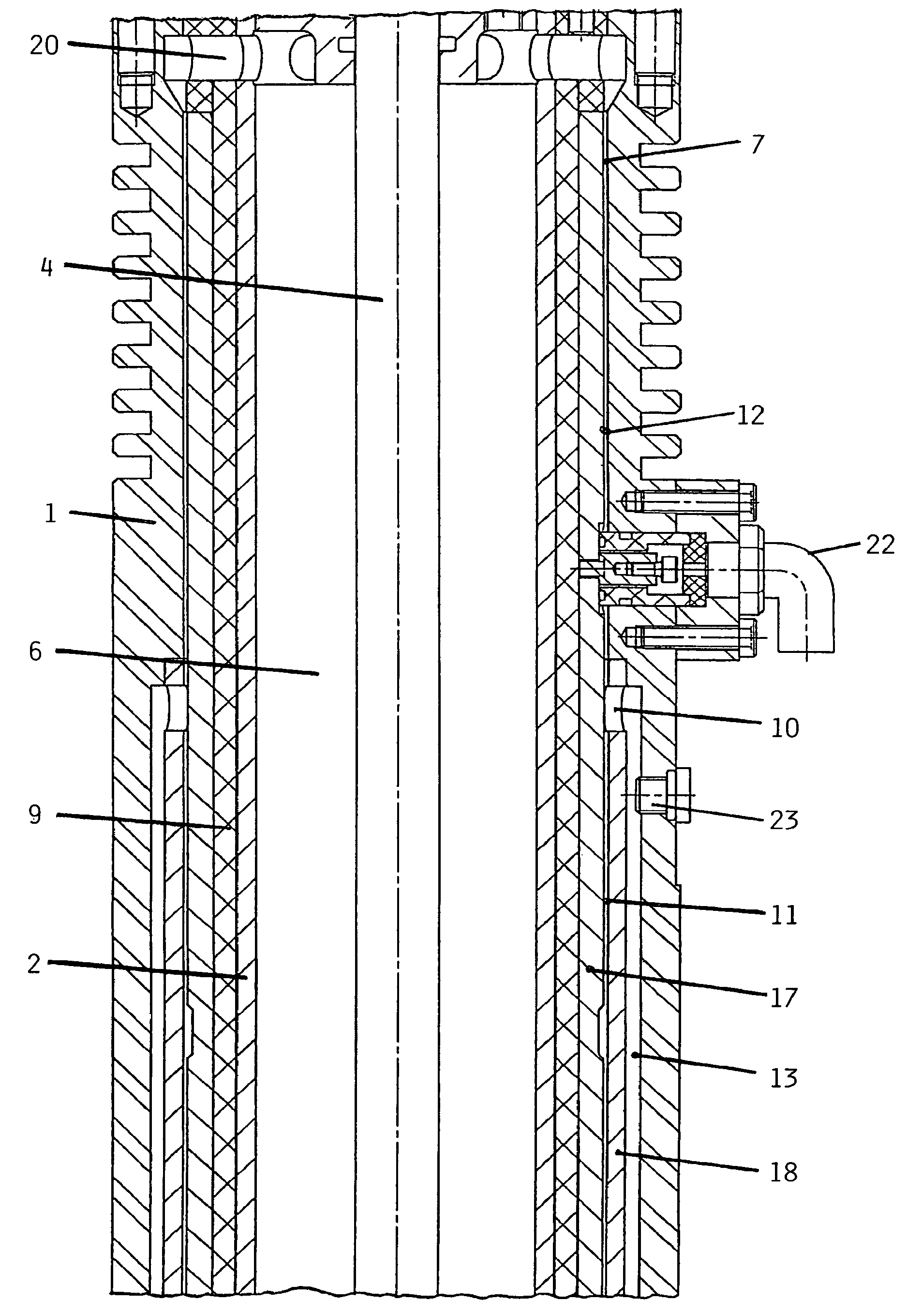
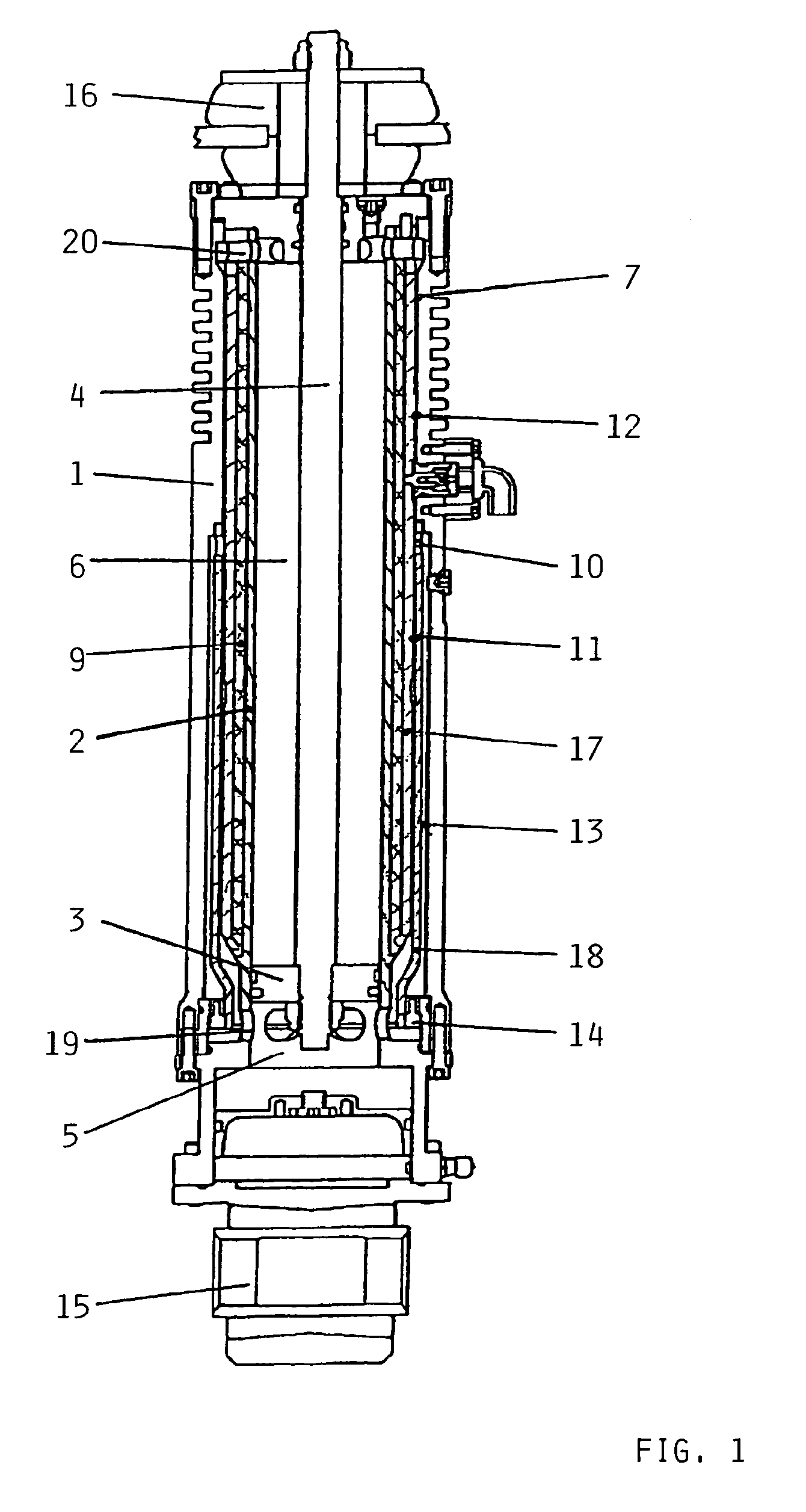
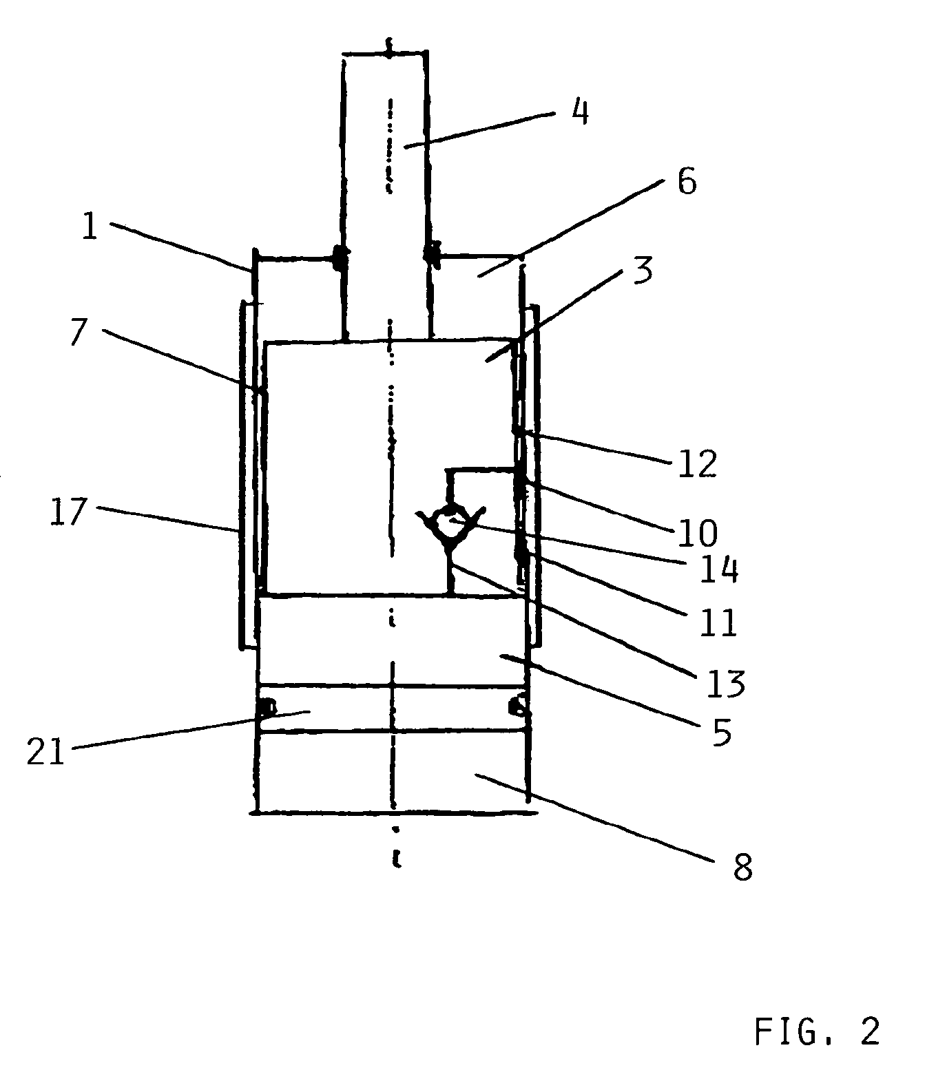
[0011]FIG. 1 of the drawing shows a controllable vibration damper with electrorheological fluid, which is embodied as a shock absorber for a motor vehicle. In this vibration damper, a piston 3 with a piston rod 4 is arranged in a cylindrical housing 1 with an inner pipe 2. Thereby the inner pipe 2 forms a pressure medium chamber, which is divided by the piston 3 into an extension chamber 6 and a retraction chamber 5. The two pressure medium chambers 5, 6 are connected with one another through a ring-shaped axial throttle gap 7 in the cylindrical housing 1. In that regard, the throttle gap 7, between its end regions, comprises a gap intersection or gating point 10, which divides the throttle gap 7 into a first throttle gap section 11 and a second throttle gap section 12. Still additionally a bypass gap 13 is connected to the gap intersection or gating point 10, whereby the bypass gap 13 is arranged parallel and coaxially to the first throttle gap section 11 in the cylindrical housing...


PUM


Abstract

A vibration damper, e.g. for damping retraction or extension springing forces on motor vehicles, includes a pressure medium cylinder in which a piston with a piston rod is axially slidably arranged. The piston divides the cylinder into first and second chambers which contain an electrorheological or magnetorheological fluid as a pressure medium. The two chambers are connected with one another through a throttle gap with at least one field generating element arranged adjacent thereto. The length of the throttle gap is divided by a gap intersection point into a first throttle gap section connected with the first chamber, and a second throttle gap section connected with the second chamber. A non-return check valve is arranged in a bypass gap connected parallel to the first throttle gap section between the gap intersection point and the first chamber.

Description

FIELD OF THE INVENTION[0001]The invention relates to a vibration damper, especially for the damping of retraction or extension springing forces on motor vehicles according to the preamble of the patent claim 1.BACKGROUND INFORMATION[0002]For today's typical chassis for motor vehicles, there is a striving that the damper forces for the extension and retraction springing respectively have a relationship in the ratio 2:1 to 4:1. If regulated hydraulic or pneumatic dampers with a characteristic field are utilized for that purpose, then the regulation quality is, however, limited with such a force relationship. Therefore, quickly regulatable vibration dampers are necessary for such regulation circuits.[0003]From the DE 103 20 005 B3, a quickly regulatable vibration damper with adjustable damping force is known, which operates with a magnetorheological fluid. This vibration damper consists of a cylinder in which a piston rod is axially movably guided. This cylinder is surrounded with a fu...

Claims


Application Information

Patent Timeline
IPC IPC(8): F16F15/03
CPCF16F9/532F16F9/535Y10T137/7837
Inventor STORK, MICHAELROSENFELDT, HORST
Owner HITACHI AUTOMOTIVE SYST EURO GMBH
Learn More