Reduced rotor assembly diameter vane pump

a vane pump and rotor assembly technology, which is applied in the direction of rotary/oscillating piston pump components, machines/engines, liquid fuel engines, etc., can solve the problems of reducing the maximum speed at which the pump can be operated, the rotor assembly diameter is larger than might otherwise be desired, and the use of vane pumps, so as to reduce the overall radial size of the pump and reduce the overall radial size. , the effect of reducing th

Inactive Publication Date: 2011-08-16
MAGNA POWERTRIAN INC (US)
View PDF8 Cites 47 Cited by
  • Summary
  • Abstract
  • Description
  • Claims
  • Application Information

AI Technical Summary

Benefits of technology

[0007]According to a first aspect of the present invention, there is provided a vane pump, comprising: a pump chamber, a rotor assembly rotatably received in the pump chamber, the rotor assembly comprising: a rotor having a circular rotor head with a cylindrical wall extending therefrom and an integrally formed drive shaft extending opposite the cylindrical wall; a set of vanes slidably extending through slots formed in the cylindrical wall of the rotor head; and a vane ring located within the cylindrical wall of the rotor head and engaging a substantial portion of the radially inner tip of each vane to maintain the radially outer tip of each vane in contact with a wall of the pump chamber as the rotor rotates and preventing each vane from tilting out of the plane of rotation of the rotor.
[0008]According to another aspect of the present invention, there is provided a variable displacement vane pump, comprising: a pump chamber; a control ring pivotally mounted within the pump chamber; a rotor assembly rotatably received in the pump chamber within the control ring, the rotor assembly comprising: a rotor having a circular rotor head with a cylindrical wall extending therefrom and an integrally formed drive shaft extending opposite the cylindrical wall; a set of vanes slidably extending through slots formed in the cylindrical wall of the rotor head; and a vane ring located within the cylindrical wall of the rotor head to maintain the radially outer tip of each vane in contact with a wall of the control ring as the rotor rotates and to prevent each vane from tilting out of the plane of rotation of the rotor.
[0010]The present invention provides a vane pump with a reduced rotor assembly diameter which reduces the overall radial size of the pump and which permits operation of the pump at a higher speed, in comparison to conventional vane pumps, for a given working fluid and pump rate. The rotor includes an integrally formed drive shaft and a cylindrical rotor head. The vane pump of the present invention is believed to be particularly suited to use as an engine lubricating oil pump in a dynamic balancer for an internal combustion engine wherein available packaging volumes are relatively small and wherein the operating speed of the pump can be relatively high but can also be used in a variety of other applications including automatic transmissions and non-automotive systems.

Problems solved by technology

While vane pumps provide a number of features and advantages, they do suffer from a disadvantage in that their rotor design and construction has resulted in a rotor assembly diameter which is larger than might otherwise be desired.
This relatively large rotor assembly diameter has prevented the use of vane pumps when insufficient packaging space (i.e.—installation or mounting volume) is available for the pump.
Further, as the operating speed of a vane pump is limited to rotational speeds which keep the tip speed of the vanes below the velocity at which the working fluid will cavitate (causing damage and / or excessive wear), the larger the rotor assembly diameter is the slower the maximum speed at which the pump can be operated.

Method used


Image

  • Reduced rotor assembly diameter vane pump
  • Reduced rotor assembly diameter vane pump
  • Reduced rotor assembly diameter vane pump

Examples


Embodiment Construction

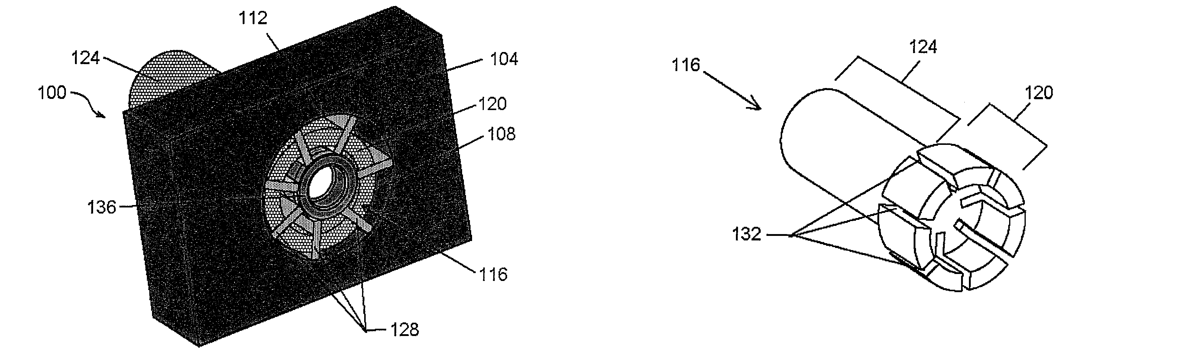
[0020]As used herein, the terms “rotor assembly diameter” and the like are intended to comprise a measure of the maximum extent to which the radially outer tip of a vane extends from the center of revolution of the rotor, as the rotor assembly makes a revolution.

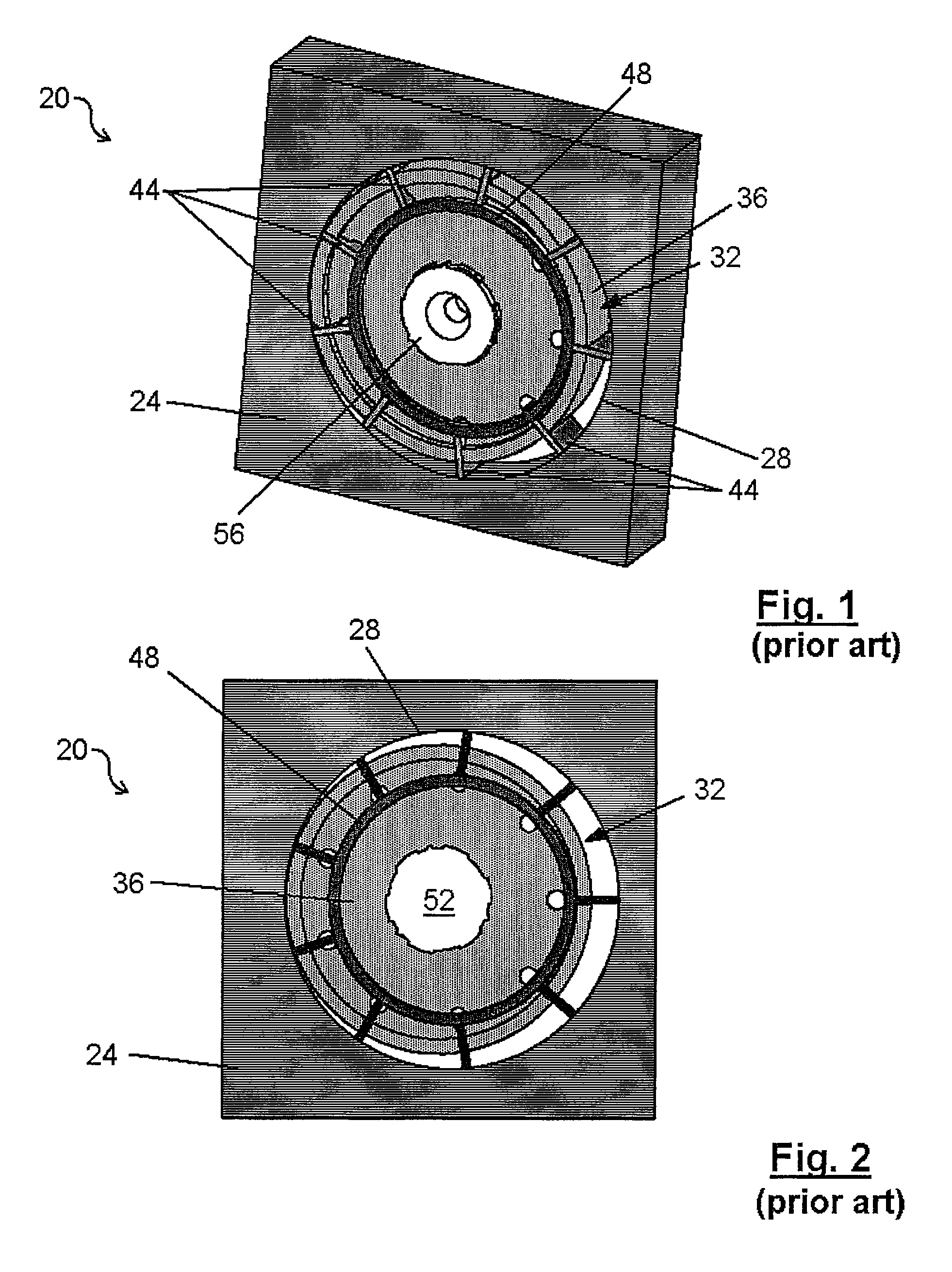
[0021]A prior art vane pump is indicated generally at 20 in FIGS. 1 and 2. As illustrated, pump 20 includes a rotor housing 24 which defines a pump chamber 28 in which a rotor assembly 32 is located.

[0022]Rotor assembly 32 includes a rotor 36 with a set of radially extending slots formed therein in which a set of pump vanes 44 are slidably retained. A vane ring 48 abuts the inner ends of vanes 44 and ensures that the outer ends of vanes 44 remain in engagement with the wall of pump chamber 28 as rotor36 rotates. Rotor 36 further includes an indexed center bore 52 in which a drive shaft 56 is received such that rotation of drive shaft 56 rotates rotor 36.

[0023]As will be apparent, the smallest possible diameter of rotor 36 is...


PUM

PropertyMeasurementUnit
lengthaaaaaaaaaa
displacementaaaaaaaaaa
thicknessaaaaaaaaaa

Abstract

A vane pump with a reduced rotor diameter is provided. The reduced rotor diameter allows a reduction in the overall size of the pump which allows the pump to be used in circumstances wherein sufficient packaging volume does not exist for conventional vane pumps. Further, the reduced rotor diameter permits operation of the pump at a higher speed, in comparison to conventional vane pumps, for a given working fluid and pump rate. The rotor includes an integrally formed drive shaft and a cylindrical rotor head. Both fixed displacement and variable displacement embodiments are shown.

Description

CROSS-REFERENCE TO RELATED APPLICATIONS[0001]This application is the national phase under 35 U.S.C. §371 of PCT International Application No. PCT / CA2007 / 000328 which has an international filing date of Mar. 1, 2007, which designated the United States of America and which application claims the benefit of U.S. Provisional Application No. 60 / 778,155, filed Mar. 1, 2006. The entire disclosures of each of the above applications are incorporated herein by reference.FIELD OF THE INVENTION[0002]The present invention relates to a vane pump. More specifically, the present invention relates to a vane pump with a reduced rotor assembly diameter.BACKGROUND OF THE INVENTION[0003]Vane pumps are well known and are used in a wide variety of environments. In the automotive field, vane pumps are used in power steering systems, automatic transmission systems and, somewhat more recently, engine lubrication systems amongst others.[0004]While vane pumps provide a number of features and advantages, they d...

Claims


Application Information

Patent Timeline
Patent Type & Authority Patents(United States)
IPC IPC(8): F03C4/00F04C14/18F04C2/00
CPCF01C21/0836F04C2/3442F01C21/08F05C2225/12F04C14/226F04C2230/22F04C2/344F04C14/20F04C18/344F04C28/20
Inventor SHULVER, DAVID R.OLARU, STEFANWILLIAMSON, MATTHEW
Owner MAGNA POWERTRIAN INC (US)
Why Eureka
Try Eureka