Gas filtering device

a filtering device and gas technology, applied in the direction of filtration separation, combustion air/fuel air treatment, separation process, etc., can solve the problems of affecting the flow of air, so as to reduce drawbacks and increase flow resistance

Inactive Publication Date: 2011-08-16
TOYOTA JIDOSHA KK +1
View PDF32 Cites 7 Cited by
  • Summary
  • Abstract
  • Description
  • Claims
  • Application Information

AI Technical Summary

Benefits of technology

Accordingly, it is an objective of the present invention to provide a gas filtering device that suppresses drawbacks such as increase of the flow resistance due to displacement of a filter sheet and pulsation of gas.
According to an aspect of the invention, a gas filtering device including a housing, a flexible filter sheet, an inlet port, an outlet port, and a displacement restriction portion is provided. The flexible filter sheet divides the interior of the housing into an inlet chamber and an outlet chamber. The filter sheet has a portion that allows passage of gas. The inlet port is connected to the inlet chamber, and conducts gas into the inlet chamber. The outlet port is connected to the outlet chamber, and conducts gas from the inlet chamber to the outlet chamber through the filter sheet. The outlet port has an opening close to the gas passing portion of the filter sheet. The displacement restricting portion restricts displacement of the gas passing portion toward the opening.

Problems solved by technology

Particularly, a part of the filter sheet that is close to the opening of the outlet port and allows passage of intake air is likely to be displaced since great amount of air passes through the part.
This may hinder smooth flow of air flowing into the opening of the outlet port, which increases the flow resistance in the intake system.
Also, when passing through the filter sheet, air can cause ruffling of the filter sheet.
This causes pulsation of the intake air.
Such pulsation of intake air can cause the intake performance of an internal combustion engine to deteriorate.
These drawbacks are not particularly unique to the air cleaner provided in the intake system of an internal combustion engine described above, but are commonly observed in other types of gas filtering devices provided with a flexible filter sheet.

Method used


Image

  • Gas filtering device
  • Gas filtering device
  • Gas filtering device

Examples


Embodiment Construction

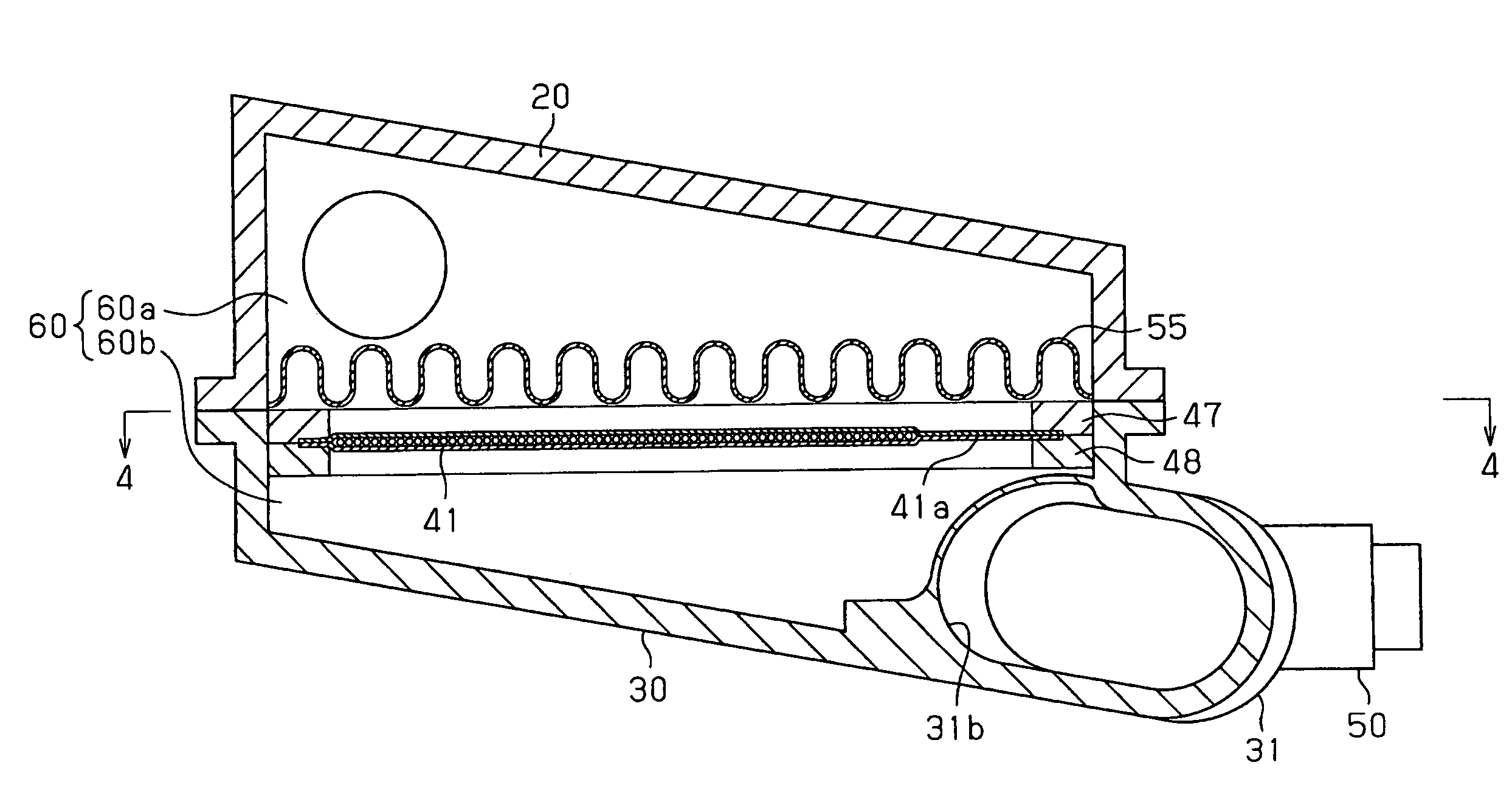
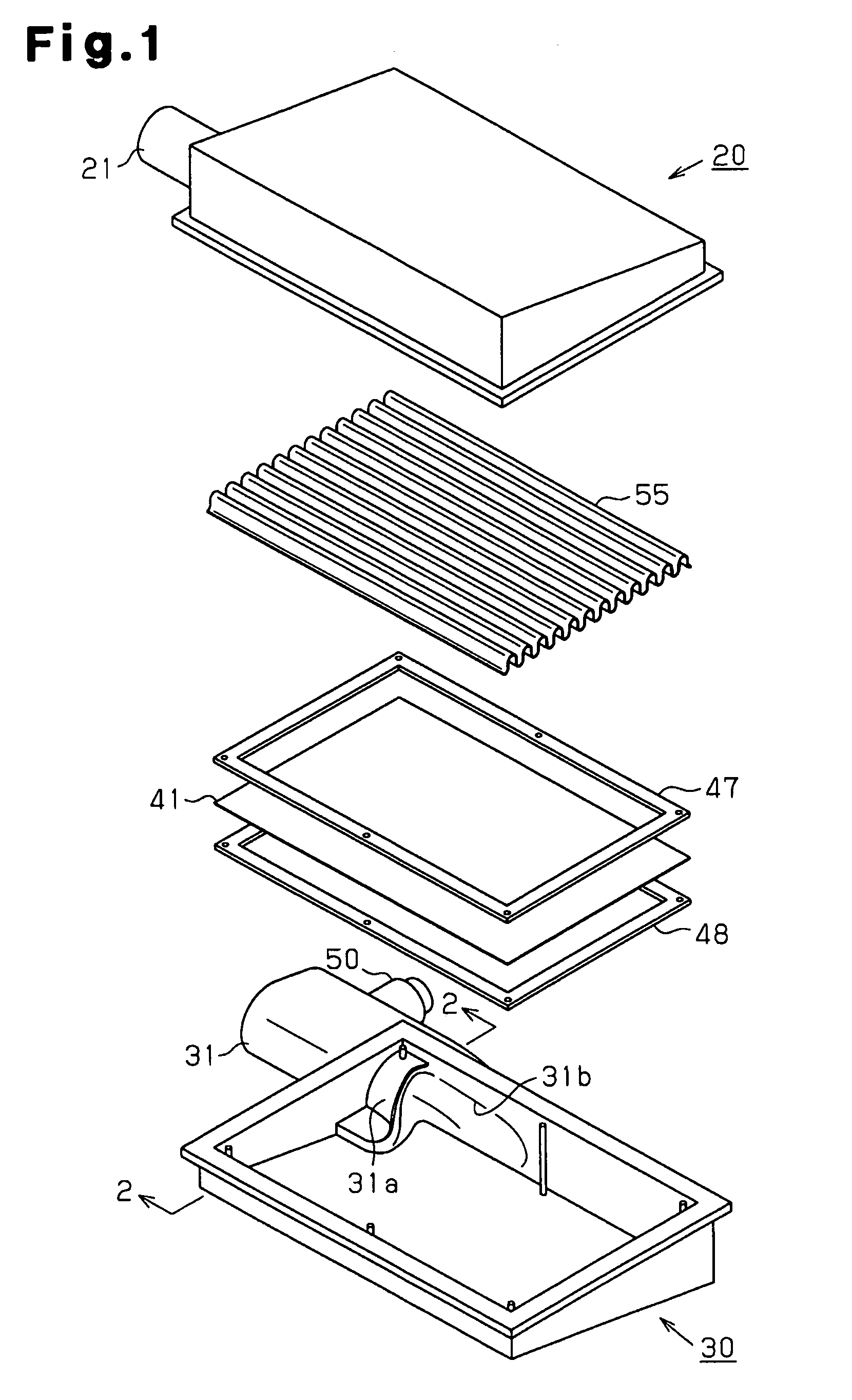
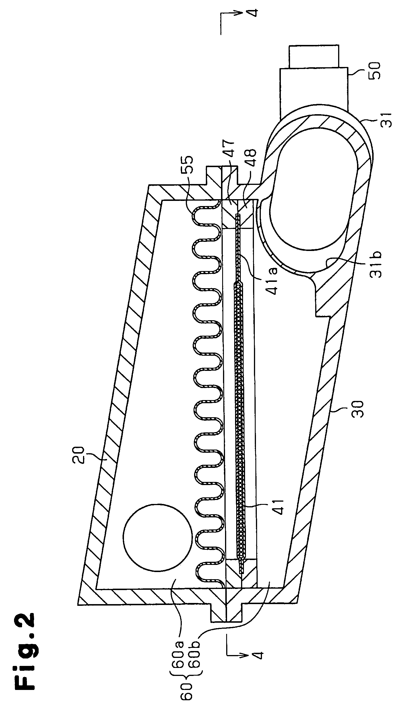
An air cleaner according to one embodiment of the present invention will be described with reference to FIGS. 1 to 4. The air cleaner is mounted in an intake system of an internal combustion engine. FIG. 1 is an exploded perspective view illustrating the air cleaner, and FIG. 2 is a cross-sectional view taken along line 2-2 of FIG. 1, illustrating the air cleaner in the assembled state. FIG. 3 is a partially enlarged view of FIG. 2.

As shown in FIGS. 1 and 2, the air cleaner, which functions as a gas filtering device, has an inlet housing 20 and an outlet housing 30. The housings 20, 30 are airtightly fixed to each other with fastening members (not shown). A filter chamber 60, which is defined by the housings 20, 30, accommodates a trap element 55 and a filter sheet 41 in an overlapping manner. The trap element 55 traps foreign matter such as dust in air and the filter sheet 41 adsorbs fuel vapor. The trap element 55 and the filter sheet 41 divide the filter chamber 60 into an inlet ...


PUM

PropertyMeasurementUnit
flexibleaaaaaaaaaa
rigidityaaaaaaaaaa
thermoplasticaaaaaaaaaa

Abstract

A gas filtering device includes a housing (20,30), a flexible filter sheet (41), an inlet port (21), an outlet port (31), and a displacement restriction portion (41a) is provided. The flexible filter sheet (41) divides the interior of the housing into an inlet chamber and an outlet chamber. The filter sheet (41) has a portion that allows passage of gas. The inlet port is connected to the inlet chamber, and conducts gas into the inlet chamber. The outlet port is connected to the outlet chamber, and conducts gas from the inlet chamber to the / outlet chamber through the filter sheet. The outlet port has an opening close to the gas passing portion of the filter sheet. The displacement restricting portion (41a) restricts displacement of the gas passing portion toward the opening.

Description

FIELD OF THE INVENTIONThe present invention relates to a gas filtering device having a flexible filter sheet.BACKGROUND OF THE INVENTIONThe intake system of a typical internal combustion engine has an air cleaner that includes a trap element for trapping foreign matter such as dust in intake air. In recent years, to suppress the leakage of fuel vapor to the atmosphere through an intake system from the combustion chamber of an internal combustion engine when the engine is not running, air cleaners have been developed that include a filter sheet for adsorbing fuel vapor. The filter sheet is located upstream of a trap element. For example, Japanese Laid-Open Patent Publication No. 2002-276486 discloses such an air cleaner. Specifically, a flexible filter sheet formed by sandwiching granular activated carbon with nonwoven fabric sheets and heat-resistant nets is arranged in a housing, while being laid on a trap element. The filter sheet and the trap element divide the interior of the ho...

Claims


Application Information

Patent Timeline
Patent Type & Authority Patents(United States)
IPC IPC(8): B01D46/52B01D53/02F02M35/024
CPCB01D46/0036B01D46/10B01D46/521F02M35/024B01D2253/102B01D2267/40B01D46/52B01D53/02
Inventor GOTO, ISAOHIZAKAE, SHIGERUTANAKA, KAZUYA
Owner TOYOTA JIDOSHA KK
Why Eureka
Try Eureka