
Apparatus for compensating for error of time-to-digital converter

a time-to-digital converter and error-correction technology, applied in the field of apparatus for compensating for errors of time-to-digital converters, can solve the problems of large power consumption and large hardware size, and achieve the effect of shortening the delay phase (t) and improving the time resolution of td

Inactive Publication Date: 2011-08-16
ELECTRONICS & TELECOMM RES INST
View PDF8 Cites 5 Cited by
  • Summary
  • Abstract
  • Description
  • Claims
  • Application Information

AI Technical Summary

Benefits of technology

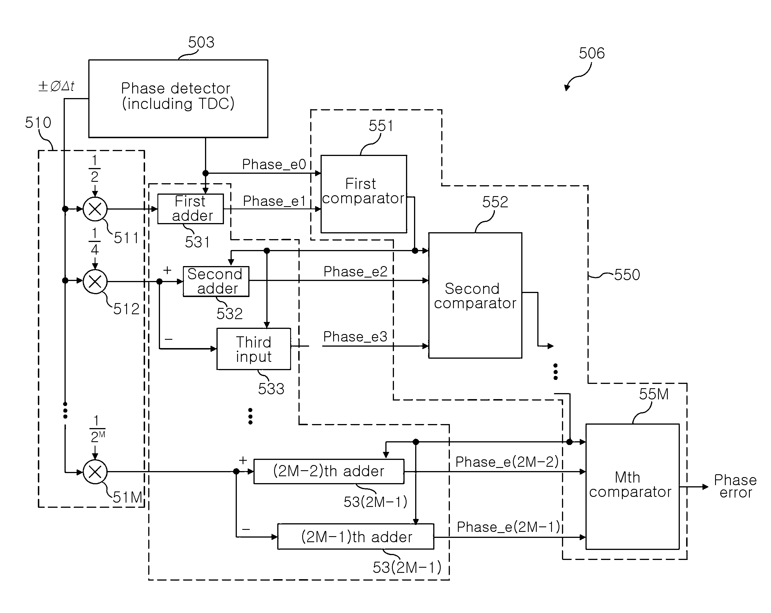
The present invention provides an apparatus for compensating for an error of a time-to-digital converter (TDC) through a digital arithmetic operation scheme, rather than using an analogwise circuit designing method that disadvantageously shortens a delay phase. The apparatus can vary the time resolution of the TDC by changing a digital control value without having to alter the design of the TDC. The apparatus includes a fragmenting and multiplying unit, an adding unit, and a comparison unit or a primary comparison unit, a multiplexer, and a secondary comparison unit. The apparatus can compensate for the TDC error by adding or subtracting a delay phase and comparing it with the phase error. The technical effect of the present invention is to improve the time resolution of the TDC by compensating for the error through a digital arithmetic operation scheme.

Problems solved by technology

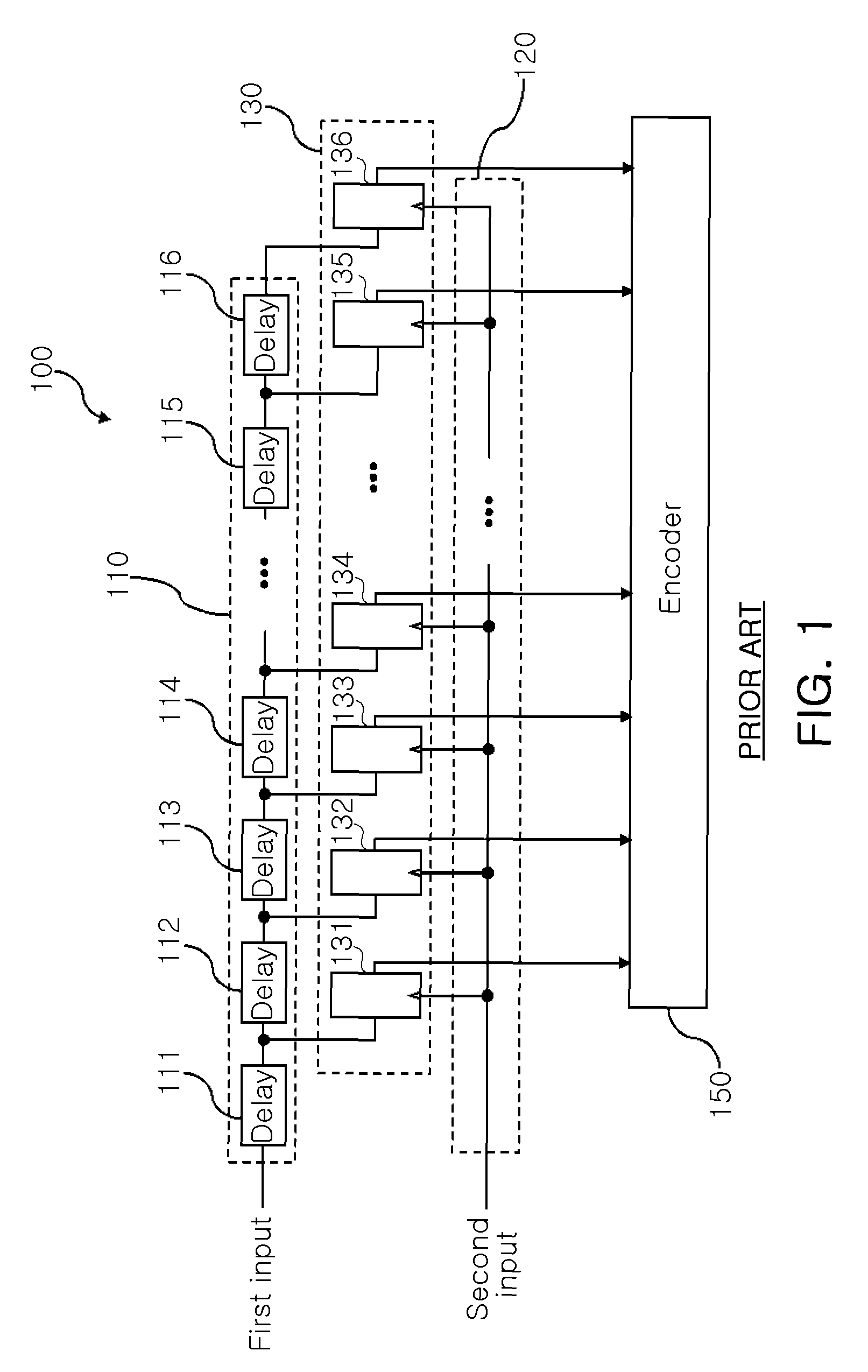
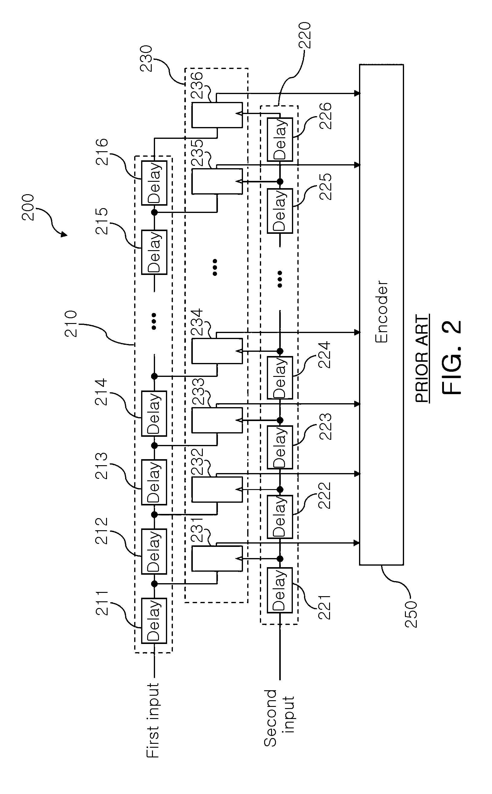
In addition, compared with the TDC 100 of FIG. 1, because the TDC 200 in FIG. 2 performs a time-to-digital conversion operation with the small time resolution, it takes time to measure the interval between the signal of the first input and that of the second input, the hardware size increases, and much power is consumed.

Method used


Image

  • Apparatus for compensating for error of time-to-digital converter
  • Apparatus for compensating for error of time-to-digital converter
  • Apparatus for compensating for error of time-to-digital converter

Examples


Embodiment Construction

[0031]Exemplary embodiments of the present invention will now be described in detail with reference to the accompanying drawings. The invention may, however, be embodied in many different forms and should not be construed as being limited to the embodiments set forth herein. Rather, these embodiments are provided so that this disclosure will be thorough and complete, and will fully convey the scope of the invention to those skilled in the art. In the drawings, the shapes and dimensions may be exaggerated for clarity, and the same reference numerals will be used throughout to designate the same or like components.

[0032]It will be understood that when an element is referred to as being “connected with” another element, it can be directly connected with the other element or intervening elements may also be present. In contrast, when an element is referred to as being “directly connected with” another element, there are no intervening elements present. In addition, unless explicitly des...


PUM


Abstract

An apparatus for compensating for an error of a time-to-digital converter (TDC) is disclosed to receive a delay phase from a phase detector including the TDC and a phase error including a TDC error and compensate for the TDC error to have a time resolution higher by N times (N is a natural number). The apparatus includes: a fragmenting and multiplying unit fragmenting the delay phase by N times (N is a natural number) to generate first to (N−1)th fragmented delay phases; an adding unit adding each of the first to the (N−1)th fragmented delay phases to the phase error to generate first to (N−1)th phase errors; and a comparison unit acquiring a phase error compensation value nearest to an actual phase error from the phase error and the first to (N−1)th phase errors.

Description

CROSS-REFERENCE TO RELATED APPLICATIONS[0001]This application claims the priorities of Korean Patent Application No. 10-2008-0121511 filed on Dec. 2, 2008 and Korean Patent Application No. 10-2009-0101148 filed on Oct. 23, 2009, in the Korean Intellectual Property Office, the disclosures of which are incorporated herein by reference.BACKGROUND OF THE INVENTION[0002]1. Field of the Invention[0003]The present invention relates to an apparatus for compensating for an error of a time-to-digital converter (TDC) capable of compensating for an error caused by a delay included in the TDC through a digital arithmetical operation scheme and simply changing the time resolution of the TDC by changing a digital control value without having to alter a device design.[0004]2. Description of the Related Art[0005]A time-to-digital converter (TDC) is used to measure a time difference between a reference signal and a comparison signal. Recently, the TDC is used in an all-digital phase locked loop in wh...

Claims


Application Information

Patent Timeline
Patent Type & Authority Patents(United States)
IPC IPC(8): H03M1/06
CPCG04F10/06H03L7/085H03L2207/50
Inventor PARK, MI JEONGMIN, BYUNG HUNLEE, JA YOLYU, HYUN KYU
Owner ELECTRONICS & TELECOMM RES INST
Learn More