Speaker array and microphone array

a technology which is applied in the field of directivity improvement of speaker array and microphone array, can solve the problems of increasing the amplitude level of the side lobes that generate the essentially unnecessary directional characteristic, and the device size of the speaker array and the microphone array is inevitably increased, so as to avoid the increase in the level of the side lobes and improve the directivity of the speaker array and the microphone array in a low frequency rang

Inactive Publication Date: 2011-08-16
YAMAHA CORP
View PDF1 Cites 55 Cited by
  • Summary
  • Abstract
  • Description
  • Claims
  • Application Information

AI Technical Summary

Benefits of technology

[0008]The present invention has been made in view of the above problems, and it is an object of the present invention to provide the technology capable of improving a directivity of a speaker array and a microphone array in a low frequency range without extension of an array length and also avoiding an increase in amplitude level of side lobes.
[0013]According to the present invention, such advantages are achieved that the directivity of the speaker array and the microphone array in a low frequency range can be improved without extension of an array length, and also an increase in level of the side lobes can be avoided.

Problems solved by technology

Therefore, such a problem existed that, in order to ensure the enough directivity in a low frequency range, a device size of the speaker array and the microphone array is inevitably increased.
Therefore, if a large amplitude is given to the stop band equal ripple to improve the directivity in a low frequency range, such a problem arose that an amplitude level of the side lobes that generate the essentially unnecessary directional characteristic is increased.

Method used


Image

  • Speaker array and microphone array
  • Speaker array and microphone array
  • Speaker array and microphone array

Examples


first embodiment

A. First Embodiment

(A-1: Configuration)

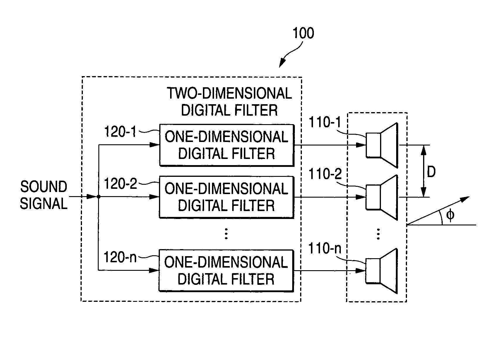
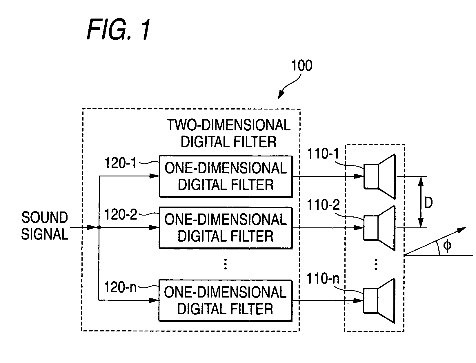
[0029]FIG. 1 is a block diagram showing an electric configuration of a speaker array 100 according to a first embodiment of the present invention. As shown in FIG. 1, the speaker array 100 has transducers (speakers in the present embodiment) 110-1, 110-2, . . . , 110-n aligned linearly at a predetermined interval (constant interval D in the present embodiment), and one-dimensional digital filters 120-1, 120-2, . . . , 120-n as many as these speakers.

[0030]In the speaker array 100 in FIG. 1, a sound signal (analog signal) supplied from an external sound source (not shown) is converted into digital data (referred to as sound data hereinafter) by an A / D converter (not shown). Then, the sound data are supplied to one-dimensional digital filters 120-i (i: a natural number of 1 to n, this is true of the following) respectively.

[0031]A filter coefficient peculiar to the speaker array according to the present invention is set previously in the one-dime...

second embodiment

B. Second Embodiment

[0063]Then, a microphone array 200 according to a second embodiment of the present invention will be explained hereunder.

[0064]FIG. 12 is a block diagram showing a configurative example of the microphone array 200 according to a second embodiment of the present invention. As apparent from the comparison between FIG. 12 and FIG. 1, a difference of the configuration of the microphone array 200 from the configuration of the speaker array 100 resides in that microphones 210-i (i: the natural number of 1 to n) for outputting the sound signal corresponding to the absorbed voice are provided in place of the speakers 110-i (i: the natural number of 1 to n).

[0065]In the microphone array 200, the sound signal output from the microphones 210-i is converted into the sound data by an A / D converter (not shown), and then input into the one-dimensional digital filters 120-i. Then, the foregoing filtering process is applied to the sound data by respective one-dimensional digital ...


PUM


Abstract

A speaker array, includes a plurality of speakers which are linearly arranged at a predetermined interval; and one-dimensional digital filters which are provided to correspond to the speakers respectively, in which predetermined filter coefficients are set previously, and which apply a filtering process to input sound data in response to the filter coefficients to output. Sound data derived by applying a digital conversion to input sound signals are supplied to respective one-dimensional digital filters. Sound signals derived by applying an analog conversion to the sound data output from respective one-dimensional digital filters are supplied to corresponding speakers to output a sound in response to the sound signals. The filter coefficients set in respective one-dimensional digital filters give an amplitude characteristic to a two-dimensional digital filter such that, when a frequency characteristic of the two-dimensional digital filter constructed by respective one-dimensional digital filters is represented by a two-dimensional frequency plane, a plurality of ripples are provided in a stop band in a section in a spatial frequency direction and also an amplitude of ripples in a non-physical area out of a plurality of ripples is larger than an amplitude of ripples in a physical area.

Description

BACKGROUND OF THE INVENTION[0001]The present invention relates to the technology to improve a directivity of a speaker array and a microphone array and, more particularly, the technology to improve a directivity in a low frequency range.[0002]The technology to form a sound field only in a particular direction or pick up a sound arriving only from a particular direction by using the speaker array or the microphone array, which is constructed by aligning a plurality of transducers such as speakers or microphones linearly at a predetermined interval, has spread popularly.[0003]By the way, in the speaker array and the microphone array of this type, it is desired that the same directional characteristic can be realized over a wide band from a high frequency range to a low frequency range. In this case, the directional characteristic in a low frequency range can be improved as an array length (a value obtained by multiplying the number of transducers by an aligned interval of the transduc...

Claims


Application Information

Patent Timeline
Patent Type & Authority Patents(United States)
IPC IPC(8): H04R3/00H04B3/00H04B5/00H03G5/00
CPCG10K11/341H04R3/005H04R3/12H04R1/403H04R1/406H04R2201/403
Inventor NISHIKAWA, KIYOSHI
Owner YAMAHA CORP
Why Eureka
Try Eureka