
Aerodynamically mistuned labyrinth seal

a technology of labyrinth seal and aerodynamic mist tuning, which is applied in the field of labyrinth seal, can solve problems such as teeth breaking

Active Publication Date: 2011-08-23
FLORIDA TURBINE TECH
View PDF6 Cites 18 Cited by
  • Summary
  • Abstract
  • Description
  • Claims
  • Application Information

AI Technical Summary

Benefits of technology

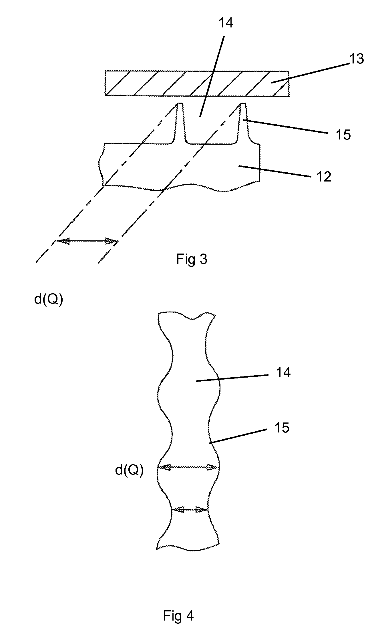
[0010]In another embodiment of the labyrinth seal of the present invention, a non-uniform knife edge to knife edge spacing is used. This design will affect the axial spacing between adjacent knife edges in the labyrinth seal which in turn affects the edge-tone frequency. This circumferential variation will prevent a lock of an acoustic mode to structural modes.
[0012]In all of these embodiments, the unsteady pressure in the seal cavities will be composed of high number of harmonics with varying phase with the seal vibratory motion. The lack of phase lock between the unsteady pressure and the vibratory mode shape will prevent the labyrinth seal from fluttering, which causes the teeth to break.
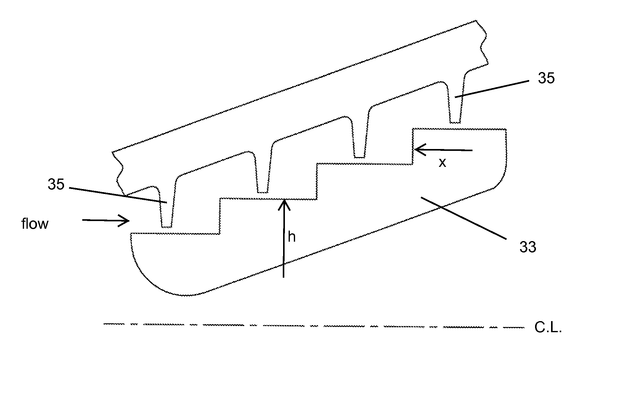
[0014]In another embodiment, a stepped labyrinth seal is used with the varying height or width formed in the individual steps of the rotor. The height of the steps can vary either sinusoidal or random, or the axial length of the steps can vary either sinusoidal or random. Also, the steps can have rounded corners such that the edge-tone phenomenon will be reduced resulting in minimal interaction between the rotor and the stator of the seal.

Problems solved by technology

This non-uniform radial gap will produce varying circumferential and axial velocities of the fluid leakage which will impact the Helmholtz and diameteral acoustic modes and prevent possible sustained resonance with the knife edges of the labyrinth seal.
The lack of phase lock between the unsteady pressure and the vibratory mode shape will prevent the labyrinth seal from fluttering, which causes the teeth to break.

Method used


Image

  • Aerodynamically mistuned labyrinth seal
  • Aerodynamically mistuned labyrinth seal
  • Aerodynamically mistuned labyrinth seal

Examples


Embodiment Construction

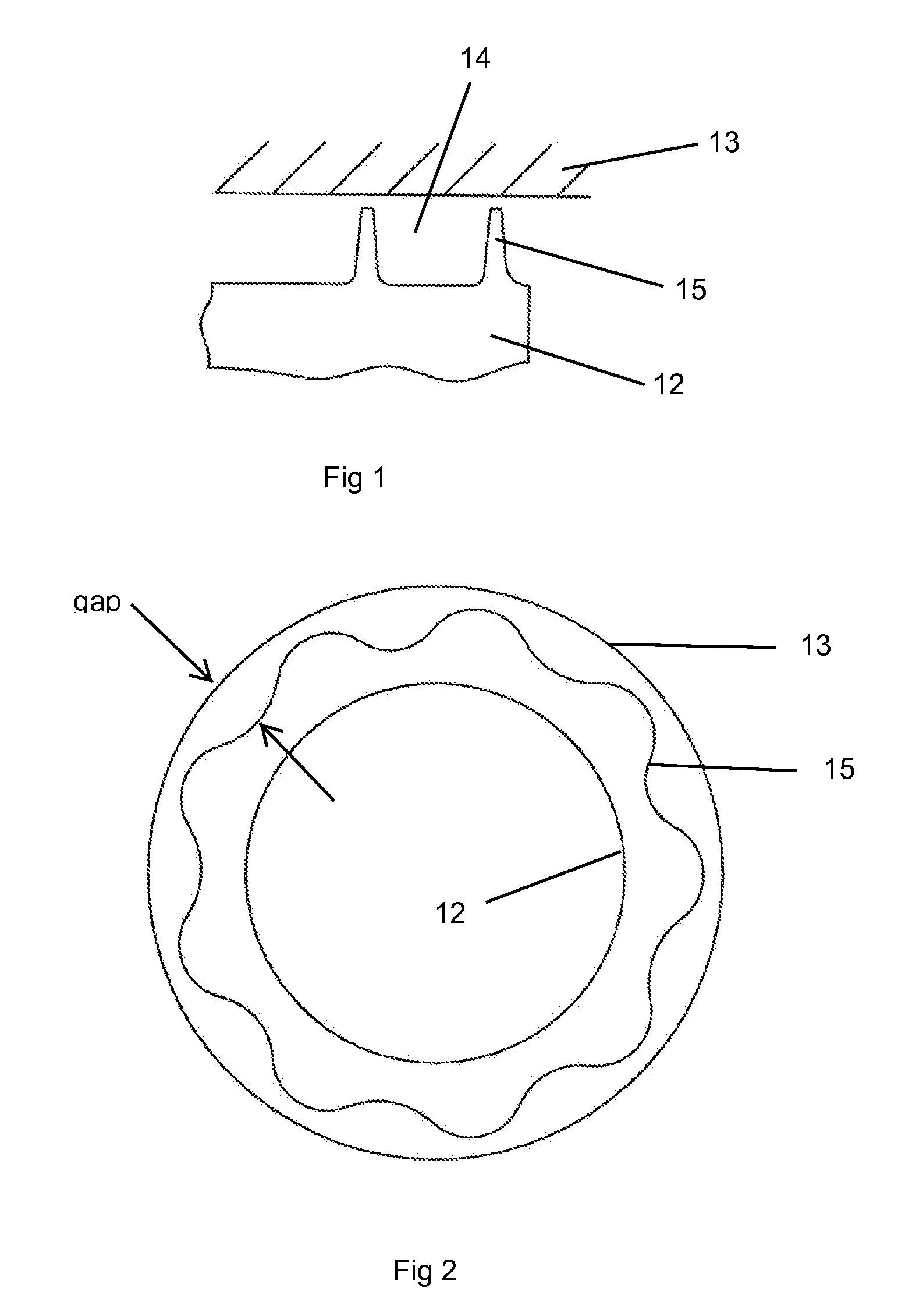
[0024]A labyrinth seal for a turbomachine is shown in FIGS. 1 and 2 and includes a stator 12 with two or more rows of knife edges or teeth 15 that extend toward a rotor 13 to form a radial gap (⊖) between a top surface of the knife edge and the inner surface of the rotor 13. In other embodiments, the knife edges can extend from the rotor with the stator forming the other end of the gap. Adjacent knife edges 15 form a cavity 14. The leakage flow across the labyrinth seal is shown by the arrow in FIG. 1. The differences between the prior art labyrinth seal and the present invention of FIG. 2 is that the upstream knife edge 15 has a varying radial height so that the knife edge radial gap also varies along the circumferential direction of the labyrinth seal. FIG. 2 shows a full annular view of the knife edge gap around the labyrinth seal with the arrows showing the gap (⊖) between the rotor 13 surface and the forward or upstream knife edge 15. In another embodiment, the second downstrea...


PUM


Abstract

A labyrinth seal having two or more knife edges in which at least one of the knife edges has a varying radial height in the circumferential direction or a cavity formed between adjacent knife edges has a varying axial width so that the leakage flow across the gap will vary around the circumference in order that excess vibrations will not develop in the knife edges and break them. The radial height of the step that forms a gap with the lab teeth varies either sinusoidal or random. An axial spacing between the step and the associated tooth can also vary either sinusoidal or random. To minimize a cavity edge-tone effect, the corners of the steps are rounded.

Description

CROSS-REFERENCE TO RELATED APPLICATIONS[0001]This application is a CONTINUATION-IN-PART of U.S. Regular patent application Ser. No. 12 / 815,063 filed on Jun. 14, 2010 and entitled AERODYNAMICALLY MISTUNED LABYRINTH SEAL.GOVERNMENT LICENSE RIGHTS[0002]None.BACKGROUND OF THE INVENTION[0003]1. Field of the Invention[0004]The present invention relates generally to a turbomachine, and more specifically for a labyrinth seal in a turbomachine.[0005]2. Description of the Related Art Including Information Disclosed Under 37 CFR 1.97 and 1.98[0006]A labyrinth seal is a mechanical seal that fits around an axle to prevent the leakage of oil or other fluids. A labyrinth seal is composed of many straight grooves that press tightly inside another axle, or inside a hole, so that the fluid has to pass through a long and difficult path to escape. Sometimes screw threads exist on the outer and inner portion. These interlock, to produce the long characteristic path which slows leakage. For labyrinth sea...

Claims


Application Information

Patent Timeline
IPC IPC(8): F16J15/447
CPCF01D11/02F16J15/4472F05D2250/70
Inventor EL-AINI, YEHIAOBRANIC, JR., GEORGE J
Owner FLORIDA TURBINE TECH
Learn More