
Splash shield systems

a technology of splash shield and shield plate, applied in the field of medical systems, can solve the problems of affecting the ability of doctors or nurses, affecting the ability of patients to see the doctor or nurse, and the high probability of contaminated fluid spreading to unwanted surfaces,

Inactive Publication Date: 2011-08-23
SCHULTZ JOSEPH P
View PDF16 Cites 13 Cited by
  • Summary
  • Abstract
  • Description
  • Claims
  • Application Information

AI Technical Summary

Benefits of technology

[0003]A primary object and feature of the present invention is to fulfill the above-mentioned needs by the provision of an improved splash shield system. A further primary object and feature of this invention is to provide a splash shield system which provides a horizontal vector to the forces of the irrigation fluid on the wound. Another primary object and feature of this invention is to provide a splash shield system which easily accommodates connection to a variety of different sources of irrigation fluid. Another primary object and feature of the present invention is to provide such a splash shield system which is efficient, inexpensive, and handy. Another primary object and feature of the present invention is to provide such a splash shield system which can be easily manipulated by the user to direct the irrigation fluid to different locations. Other objects and features of this invention will become apparent with reference to the following specification and claims.SUMMARY OF THE INVENTION AND ADVANTAGES

Problems solved by technology

Unfortunately, when using large volumes or high amounts of pressures, there is a high likelihood of contaminated fluid spreading to unwanted surfaces, including splashing onto a health care provider or drenching the patient.
This is undesirable as the risk of spreading of disease is heightened and there are undesirable effects of getting a patient wet (for example, a trauma patient with multiple wounds might be hypothermic from a large amount of irrigation fluid evaporating on his body, or a child with a facial laceration might become hypothermic from the excess fluid wetting its clothing during the winter).
This is also an inconvenience for otherwise healthy patients.
This may be uncomfortable for the patient in a busy emergency room; and the time necessary for the patient to disrobe would delay a doctor's or nurse's ability to treat such patient or other waiting patients more expeditiously.
These disadvantages will decrease the incentive for an operator, such as a physician, to appropriately use optimal large volumes of irrigation fluid; and therefore the risk of wound complications will increase.
Still another disadvantage, in addition to the small diameter discharge port of a prior art syringe shield, is that when an operator empties a syringe using a prior art syringe shield, the operator must actively detach the shield from the syringe to refill the syringe to apply a large volume of fluid to a wound because of the small volume capacity of syringes.

Method used


Image

  • Splash shield systems
  • Splash shield systems
  • Splash shield systems

Examples


Embodiment Construction

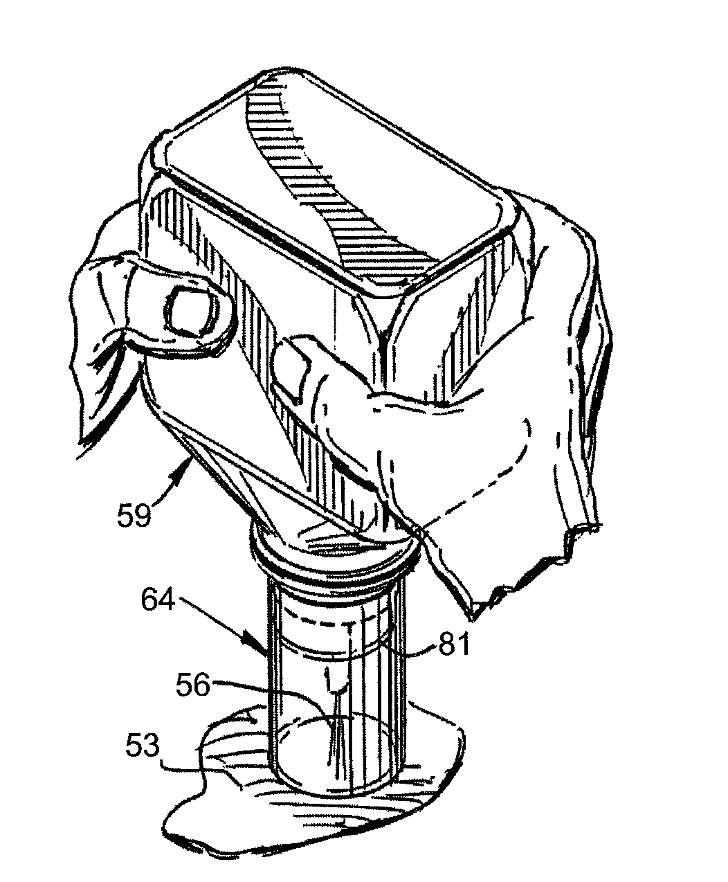
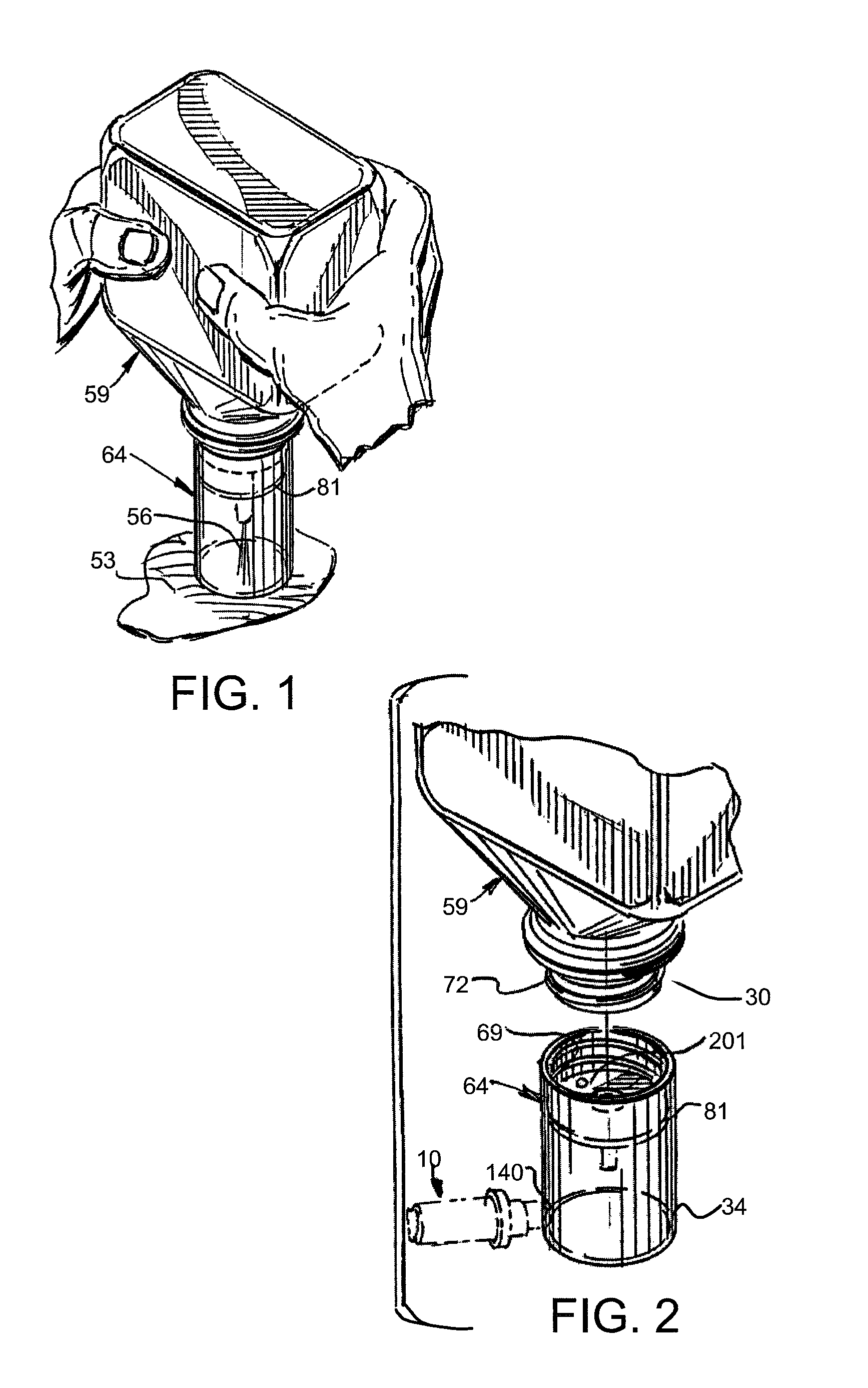
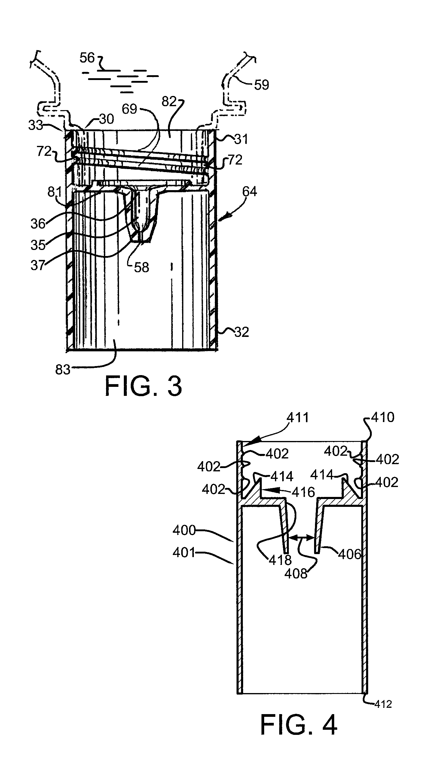
[0065]FIG. 1 is a perspective view of a preferred embodiment of a splash shield system according to the present invention, showing use of splash shield 64 attached to wide mouth irrigation squeeze bottle 59. Preferably, wide mouth irrigation squeeze bottle 59 comprises a standard high volume plastic squeeze bottle of sterile fluid (sometimes also referred to herein as irrigation fluid), as shown. Preferably, wide mouth irrigation squeeze bottle 59 comprises a volume of at least about 250 cc. Preferably, wide mouth irrigation squeeze bottle 59 comprises a volume less than about 1750 cc. Preferably, wide mouth irrigation squeeze bottle 59 comprises bottle neck finish portion 30, as shown. Preferably, bottle neck finish portion 30 comprises an inner diameter between about ¾ inches and about 1½ inches, most preferably between about ⅘ inches and about 1¼ inches. Preferably, bottle neck finish portion 30 comprises an outer diameter between about ⅘ inches and about 1¾ inches. Preferably, w...


PUM


Abstract

Splash shield systems for use with wide mouth irrigation squeeze bottles and other irrigation fluid sources.

Description

CROSS-REFERENCE TO RELATED APPLICATIONS[0001]The present application is a continuation-in-part of related U.S. utility patent application Ser. No. 11 / 317,758, filed Dec. 23, 2005, entitled “SPLASH SHIELD SYSTEM”, which is a continuation-in-part of U.S. utility patent application Ser. No. 10 / 245,241, filed Sep. 17, 2002, entitled “SPLASH SHIELD SYSTEM”, which is a continuation-in-part of U.S. utility patent application Ser. No. 10 / 123,966, filed Apr. 16, 2002, entitled “MEDICAL COMPONENT SYSTEM”, which is a continuation-in-part of related U.S. utility patent application Ser. No. 09 / 484,666, filed Jan. 18, 2000, entitled “MEDICAL COMPONENT SYSTEM”, and is related to and claims priority from prior provisional application Ser. No. 60 / 803,109, filed May 24, 2006, entitled “SPLASH SHIELD SYSTEM”, all of which are incorporated herein by this reference, and which are not admitted to be prior art with respect to the present invention by the mention in this cross-reference section.BACKGROUND ...

Claims


Application Information

Patent Timeline
IPC IPC(8): A61M35/00A61M31/00
CPCA61B19/42A61M3/0262A61M3/0279A61B90/05
Inventor SCHULTZ, JOSEPH P.
Owner SCHULTZ JOSEPH P
Learn More