Bone fixation implant system and method

a bone fixation and implant technology, applied in the field of bone arthrodesis, can solve the problems of time-consuming and difficult surgical procedures to implant screws or wires, and achieve the effects of enhancing stability placement, convenient removal, and fastening of nuts

Inactive Publication Date: 2011-08-23
CTL MEDICAL CORP
View PDF35 Cites 11 Cited by
  • Summary
  • Abstract
  • Description
  • Claims
  • Application Information

AI Technical Summary

Benefits of technology

[0005]The system includes an implant with a threaded screw, a distal nut with a threaded bore, and a proximal washer which may also be threaded. An instrument for implanting the implant includes a handle and a barrel terminating in a holder for the washer. A c-shaped bridge assembly has a first end connected to the barrel and a second end including a holder for the nut in axial alignment with the washer. A manually operated control on the instrument, coupled to an elongated element in the barrel, causes the washer to move toward the nut, thereby applying compressive pressure to bone portions to be fastened together. A drive mechanism disposed within the barrel has a distal end with a holder for the screw and a proximal end that is turned by a user, thereby advancing the screw through the washer to the nut to fasten the bone portions under compression. A separate control is used to release pressure on the elongated element in the barrel, enabling the implant to be easily removed from the implant once in position.
[0006]In the preferred embodiment, the controls are triggers that are squeezed toward the handle by a user. The nut may include opposing side cut-outs that extend into the threaded bore, and the holder for the nut may include a pair of opposing side tabs that engage with the cut-outs during placement of the nut. The opposing side tabs are deformed outwardly when the screw is advanced through the nut, thereby enabling the bridge assembly to be remove from the implant. The nut may further include opposing side cut-outs that do not extend into the threaded bore, with the holder for the nut include a pair of opposing outriggers that engage with the cut-outs to enhance stability placement and fastening of the nut.

Problems solved by technology

The surgical procedures that must be performed to implant the screws or wires are difficult and time consuming.

Method used


Image

  • Bone fixation implant system and method
  • Bone fixation implant system and method
  • Bone fixation implant system and method

Examples


Embodiment Construction

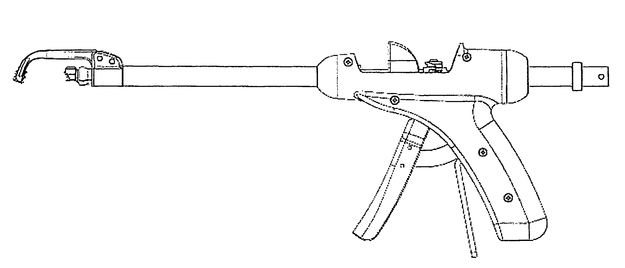
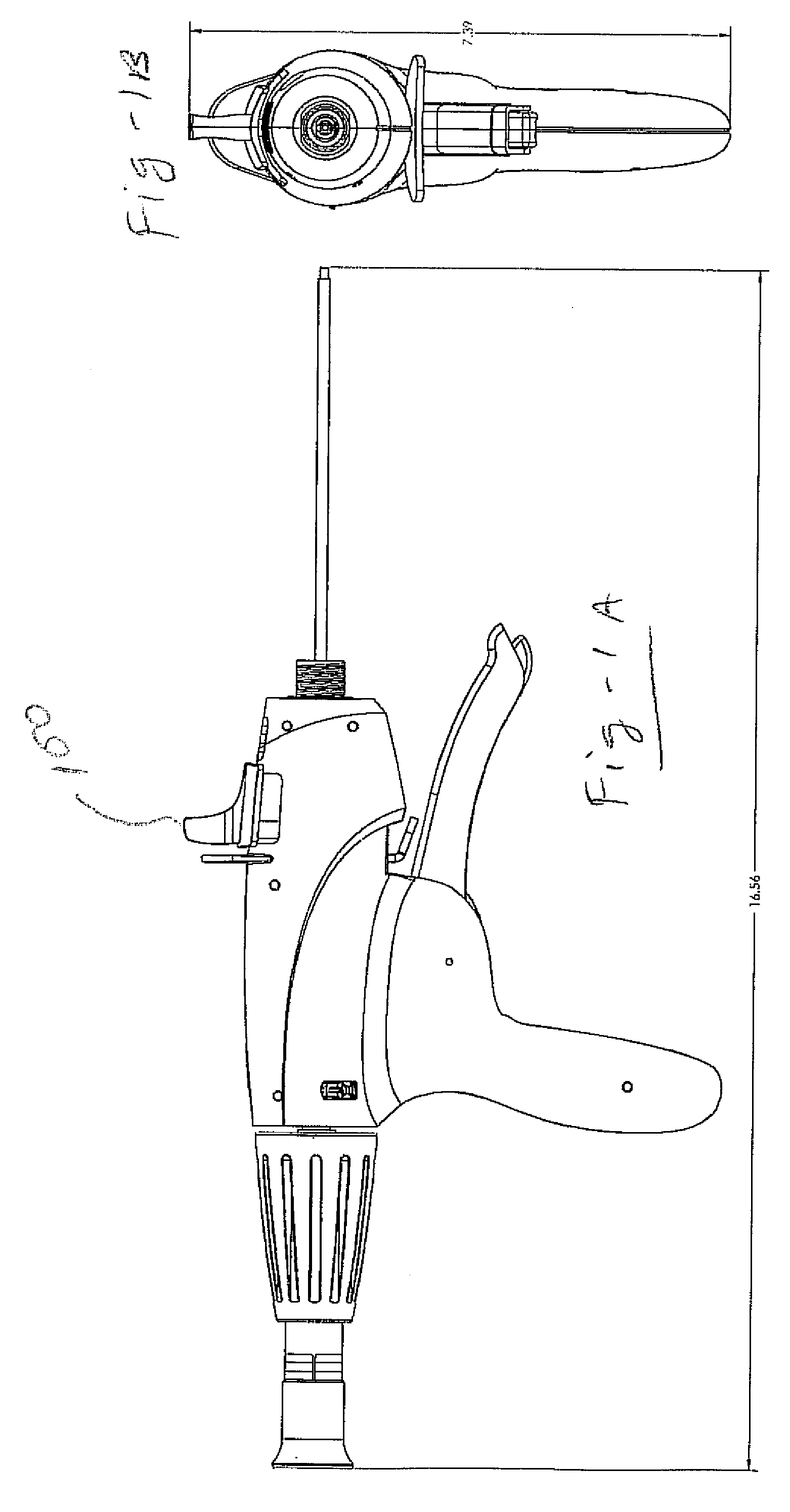
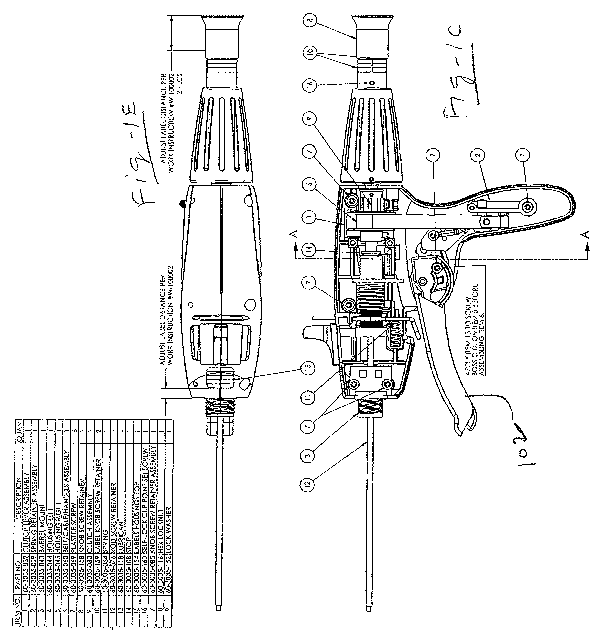
[0048]Co-pending U.S. patent application Ser. No. 10 / 973,524, the entire content of which is incorporated herein by reference, describes a bone fixation implant system and method particularly useful for percutaneous facet fixation during minimally invasive surgical procedures. The system includes an implant for bone arthrodesis and a bone fastening device. The implant includes a fastener with an elongated shaft having a head at one end and a bone-piercing point at the opposite end. A first washer has structure for engaging the head of the shaft so as to be polyaxially pivotable with respect to the head. A locking member has structure for engaging the shaft. The locking member can have a second washer pivotally engaged thereto. The bone fastening device can include an elongated cannula with a collet for detachably engaging the first washer and for advancing the first washer. Structure is provided for engaging the fastener and for advancing and rotating the fastener through the collet...


PUM


Abstract

A bone-fastening system includes an implant with a threaded screw, a distal nut with a threaded bore, and a proximal washer which may also be threaded. An instrument for implanting the implant includes a handle and a barrel terminating in a holder for the washer. A c-shaped bridge assembly has a first end connected to the barrel and a second end including a holder for the nut in axial alignment with the washer. A manually operated control on the instrument, coupled to an elongated element in the barrel, causes the washer to move toward the nut, thereby applying compressive pressure to bone portions to be fastened together. A drive mechanism disposed within the barrel has a distal end with a holder for the screw and a proximal end that is turned by a user, thereby advancing the screw through the washer to the nut to fasten the bone portions under compression. The manually operated control is preferably a trigger that is squeezed toward the handle by a user. A separate control, also preferably in the form of a trigger, is used to release pressure on the elongated element in the barrel, enabling the implant to be easily removed from the implant once in position.

Description

REFERENCE TO RELATED APPLICATIONS[0001]This application claims priority from U.S. Provisional Patent Application Ser. No. 60 / 938,886, filed May 18, 2007; and is a continuation-in-part of U.S. patent application Ser. No. 10 / 973,524, filed Oct. 26, 2004, which is a continuation-in-part of U.S. patent application Ser. No. 10 / 683,076, filed Oct. 10, 2003, which claims priority to U.S. Provisional Patent Application Ser. No. 60 / 417,543, filed Oct. 10, 2002. The entire content of each application is incorporated herein by reference.FIELD OF THE INVENTION[0002]This invention relates to bone arthrodesis, and more particularly to bone fixation implants and systems and methods for installing such implants.BACKGROUND OF THE INVENTION[0003]Bone arthrodesis or fusion is a process used to assist in the healing or stabilization of impaired bones or joints. In particular, facet arthrodesis is used to fuse the superior and inferior facet in spinal treatment operations, Prior art systems and methods ...

Claims


Application Information

Patent Timeline
Patent Type & Authority Patents(United States)
IPC IPC(8): A61B17/04
CPCA61B17/7064A61B17/8872A61B17/1757A61B2017/0023A61B17/8695A61B17/8665
Inventor FALAHEE, MARKREED, PHILBLAKE, DORISCAWLEY, TRACE R.
Owner CTL MEDICAL CORP
Why Eureka
Try Eureka