

Uncooled protective slag discharge tube
Active Publication Date: 2011-08-23
SIEMENS ENERGY GLOBAL GMBH & CO KG
View PDF5 Cites 5 Cited by
- Summary
- Abstract
- Description
- Claims
- Application Information
AI Technical Summary
Benefits of technology
[0008]By selecting a suitable material, especially Molybdenum or Tantalum, a previously complicated installation can be greatly simplified by the omission of the cooling previously required.
[0009]Since any devices built into the quench chamber increase the danger of deposits and buildups, such devices are restricted to those that are absolutely necessary. The omission of the cooling water pipes for the draft tube is a further step for simplification and for increasing the availability of the existing technology.
[0010]The choice of Molybdenum as a material enables the cooling of the protective slag discharge tube to be dispensed with. Molybdenum exhibits the necessary form stability up to 1800° C. and resistance to chemicals (in a reducing atmosphere).
[0011]As well as Molybdenum there is a plurality of Molybdenum alloys that are more expensive but that have specific advantages over pure Molybdenum (especially resistant to glasses, slag and liquid metals). The Molybdenum-Tungsten used in the glass industry (MoW70—70% by weight Mo, 30% by weight W or MoW50—50% by weight Mo, 50% by weight W) deserves especial mention. Tantalum is suitable as a further temperature-resistant metal because of its better cold workability.
Problems solved by technology
This protective tube is subjected to high thermal stresses and thereby to high levels of wear.
In particular when short-duration buildups of slag deposits divert the stream of crude gas heated up to between 1300° C. and 1800° C., damage to this protective tube can result.
Method used
View moreImage
Smart ImageViewing Examples

Examples
Embodiment Construction
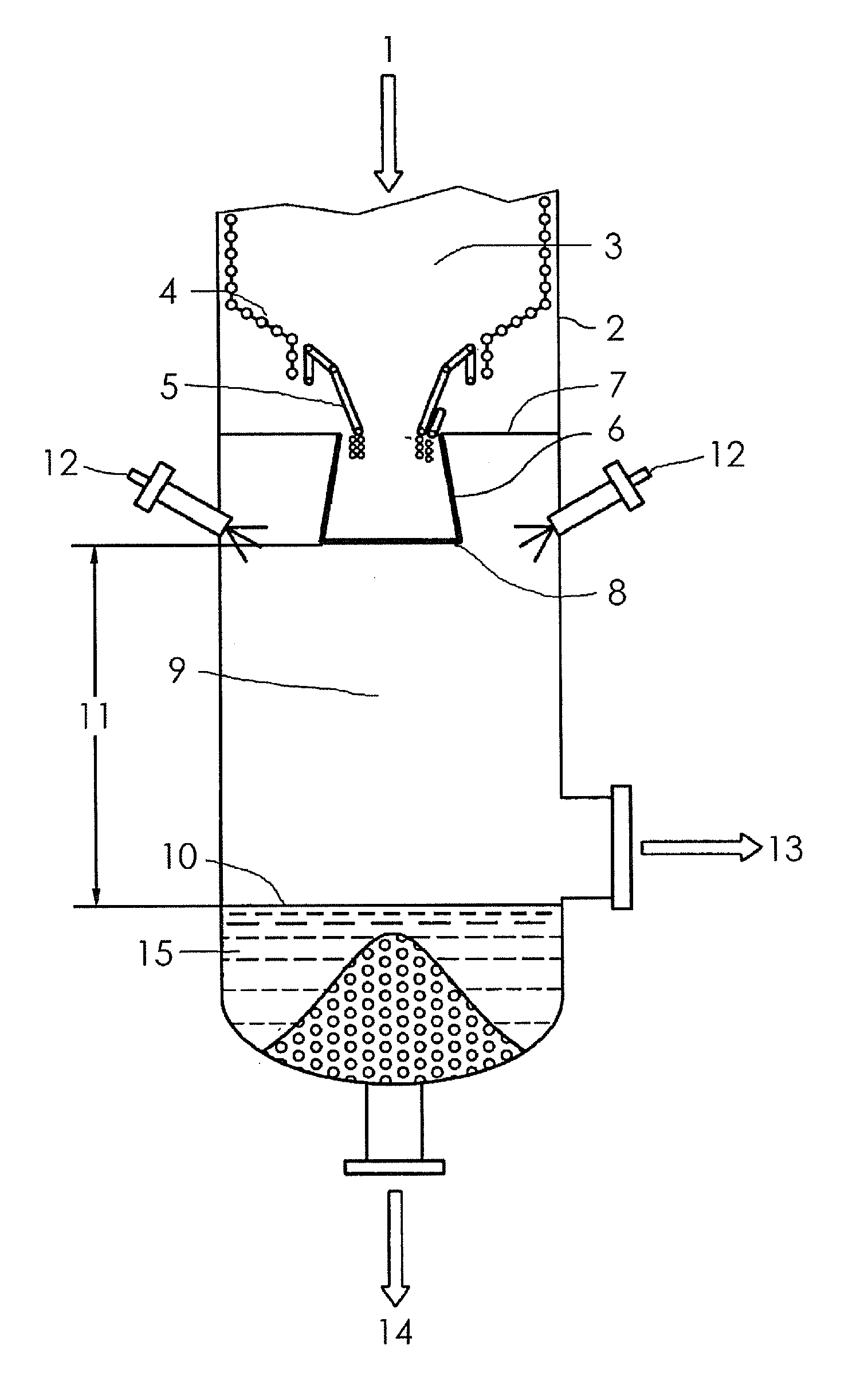
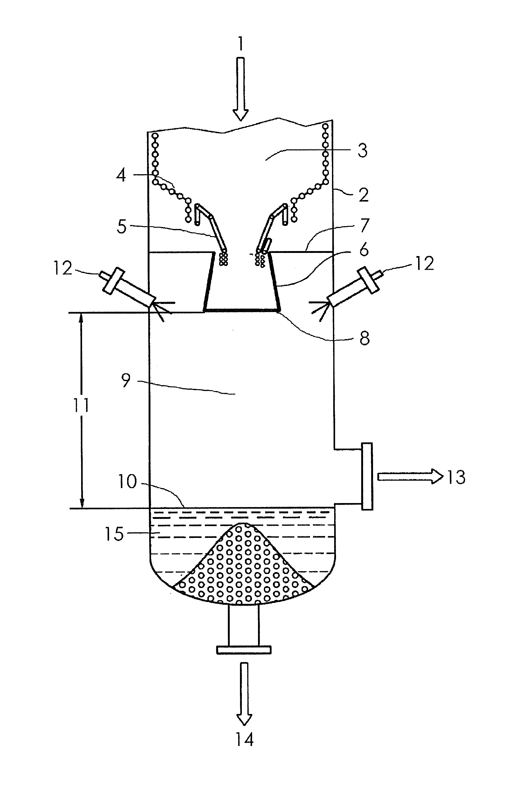
[0013]At the top of the FIGURE, crude gas and slag 1 exit reaction chamber 3 near the top of the reactor 2. The reaction chamber 3 has a bottom 4. A draft tube 6 is in communication with a crude gas and slag discharge outlet 5 of the bottom 4 of the reaction chamber 3. The draft tube 6 is supported by an apparatus 7 attached to reactor 2. The bottom 8 of draft tube 6 is above the water line 10 of the sump 15 by a distance 11. Cooling water is injected via water injection nozzle 12 into the quench chamber 9. The crude gas discharge tube 13 is located above the water line 10 of the sump 15. A discharge tube 14 is located at the bottom of the sump 15.
Login to View More PUM
 Abstract
A reactor is proposed for entrained flow gasification for operation with pulverized or liquid fuels, with an externally cooled draft tube protecting the slag discharge outlet. An outlet of the draft tube remains above a water line of a sump of the reactor and is formed from Molybdenum, an alloy featuring molybdenum, Tantalum or an alloy featuring Tantalum.
Description
CROSS REFERENCE TO RELATED APPLICATIONS[0001]This application claims the benefits of German application No. 10 2007 030 779.0 filed Jul. 3, 2007 and is incorporated by reference herein in its entirety.FIELD OF INVENTION[0002]The subject matter of the application relates to a reactor for entrained flow gasification and a draft tube for a reactor for entrained flow gasification.BACKGROUND OF THE INVENTION[0003]A known embodiment of a reactor for entrained flow gasification has a common reactor outlet for molten slag and the hot crude gas (see FIGURE, reference symbol 5) into the quench chamber. The hot crude gas is rapidly cooled off there by the injection of water. The molten slag simultaneously solidifies and falls into the quench chamber sump. The protective slag discharge tube (also called the draft tube) located at the outlet of the reactor has the task of protecting the slag discharge against direct contact with quench water to prevent the slag solidifying and thereby to prevent...
Claims
Login to View More Application Information
Patent Timeline
 IPC IPC(8): B01J8/00C10J1/207
CPCC10J3/485C10J3/82C10J3/84C10J2200/09C10J2300/1634
InventorKOHLER, MATTHIASLAMP, JOACHIM
OwnerSIEMENS ENERGY GLOBAL GMBH & CO KG