Liquid recovery system, immersion exposure apparatus, immersion exposing method, and device fabricating method

a technology of immersion exposure and liquid recovery, which is applied in the field of liquid recovery system, immersion exposure apparatus, immersion exposing method, and device fabricating method, can solve the problems of exposure failure, liquid will not be completely recovered, leakage or remain on the substrate, etc., and achieve the effect of preventing the fabrication of defective devices, preventing exposure failure, and satisfactorily recovering liquid

Inactive Publication Date: 2011-08-23
NIKON CORP
View PDF42 Cites 44 Cited by
  • Summary
  • Abstract
  • Description
  • Claims
  • Application Information

AI Technical Summary

Benefits of technology

[0009]According to the first aspect of the invention, it is possible to recover the liquid satisfactorily.
[0011]According to the second aspect of the invention, it is possible to recover the liquid satisfactorily, and thereby to prevent exposure failure.
[0013]According to the third aspect of the invention, it is possible to prevent the fabrication of defective devices.
[0015]According to the fourth aspect of the invention, it is possible to recover the liquid satisfactorily, and thereby to prevent exposure failure.
[0017]According to the fifth aspect of the invention, it is possible to prevent the fabrication of defective devices.
[0018]According to the some aspects of the present invention, it is possible to recover the liquid satisfactorily and thereby to prevent exposure failure. Accordingly, it is possible to prevent the fabrication of defective devices.

Problems solved by technology

If the moving speed of a substrate is increased, then there is a possibility that the liquid will not be completely recovered, or that it will leak or remain on the substrate.
If such problems arise, then there is a possibility that exposure failures will occur, leading to, for example, defects in the pattern formed on the substrate.
As a result, there is a possibility mat defective devices will be fabricated.

Method used


Image

  • Liquid recovery system, immersion exposure apparatus, immersion exposing method, and device fabricating method
  • Liquid recovery system, immersion exposure apparatus, immersion exposing method, and device fabricating method
  • Liquid recovery system, immersion exposure apparatus, immersion exposing method, and device fabricating method

Examples


first embodiment

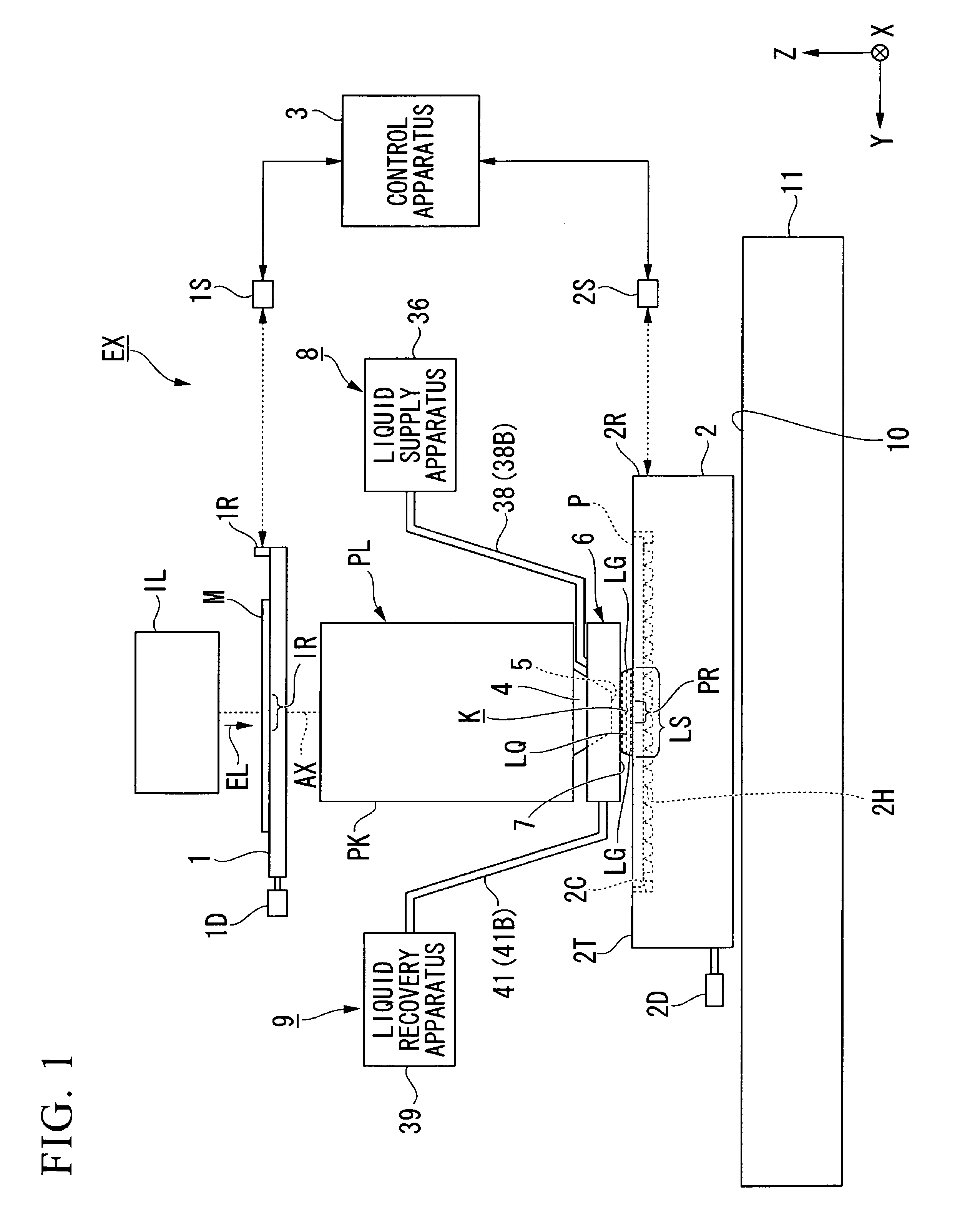
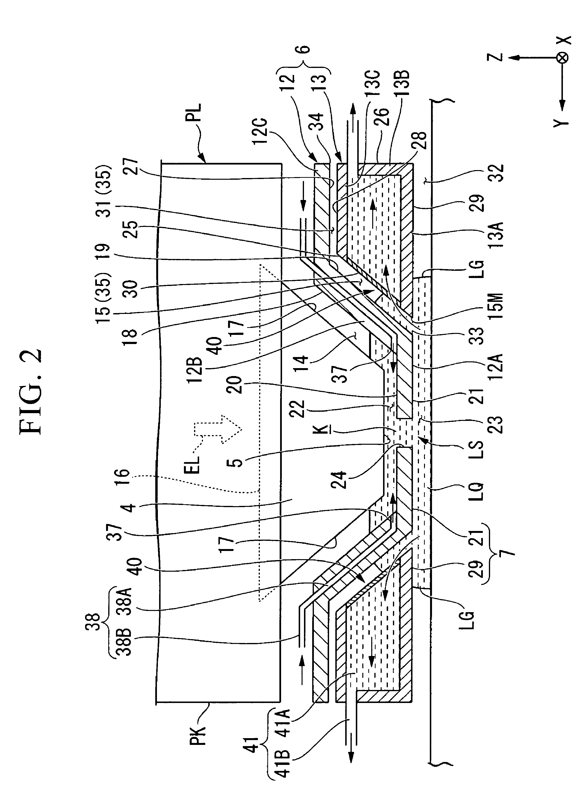
[0039]A first embodiment will now be explained. FIG. 1 is a schematic block diagram that shows an exposure apparatus EX according to the first embodiment. In FIG. 1, the exposure apparatus EX comprises a mask stage 1, which is capable of moving while holding a mask M, a substrate stage 2, which is capable of moving while holding a substrate P, an illumination system IL, which illuminates the mask M with exposure light EL, a projection optical system PL, which projects an image of a pattern of the mask M that is illuminated by the exposure light EL onto the substrate P, and a control apparatus 3 that controls the operation of the entire exposure apparatus EX.

[0040]Furthermore, the substrate P referenced herein is a substrate for fabricating a device and can include one that has a base material, such as a semiconductor wafer such as a silicon wafer, whereon a film, such as a photosensitive material (photoresist), is formed, or include one on which various types of membrane such as a p...

second embodiment

[0117]The following explains a second embodiment. In the explanation below, constituent parts that are identical or equivalent to those in the embodiment discussed above are assigned identical symbols, and the explanations thereof are therefore abbreviated or omitted.

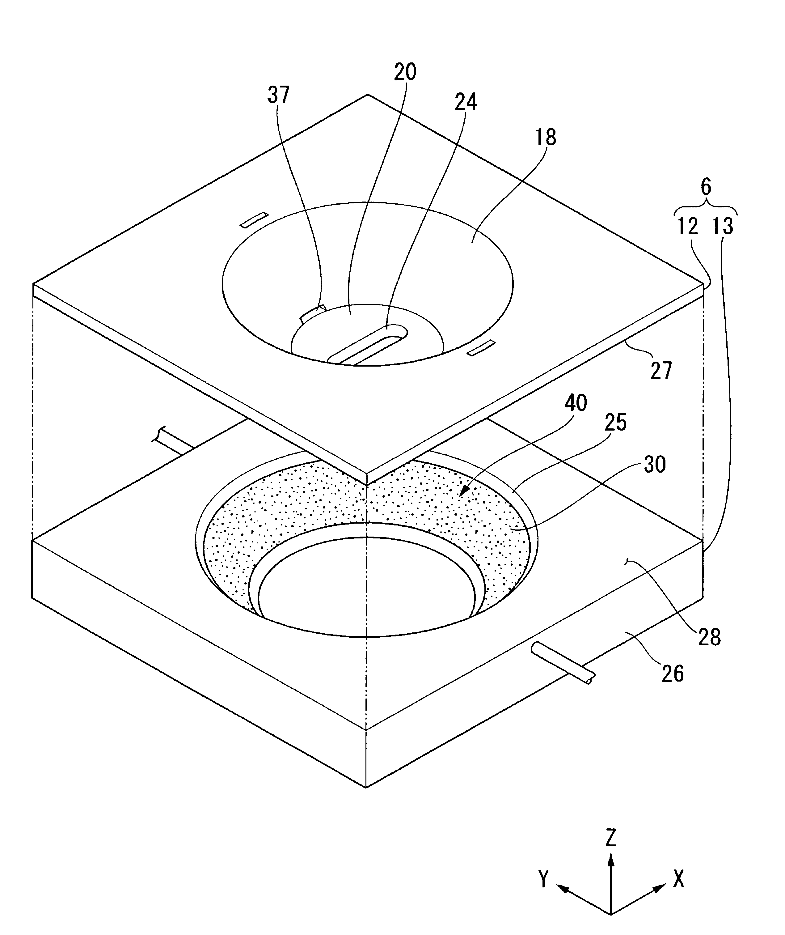
[0118]FIGS. 7A and 7B show a second embodiment and comprises schematic drawings that show a state wherein the front surface of the substrate P moves in the −Y direction with respect to the optical path of the exposure light EL and the immersion space LS; here, FIG. 7A is a side cross sectional view and FIG. 7B shows the liquid immersion member 6 viewed from below. The configuration of the liquid immersion member 6 and the like is equivalent to that of the first embodiment discussed above. The first embodiment discussed above explained an exemplary case wherein the entire first opening 33 is covered with the liquid LQ even during the movement of the substrate P; however, as shown in FIGS. 7A and 7B, part (a portion on th...

third embodiment

[0123]The following explains a third embodiment. The embodiments discussed above explained an exemplary case wherein the first land surface 21 and the second land surface 29 are substantially flush, but they do not have to be parallel.

[0124]FIG. 8 is a side cross sectional view that shows a liquid immersion member 6B according to the third embodiment, and FIG. 9 is a view of the same, from below. As shown in FIG. 8 and FIG. 9, in the present embodiment, the second land surface 29 is disposed at a position that is spaced apart from the front surface of the substrate P more than the first land surface 21 is. In the present embodiment, the second land surface 29 of the second member 13 is inclined with respect to the first land surface 21 of the first member 12. Specifically, the second land surface 29 is inclined so that the spacing to the front surface of the substrate P increases as it becomes increasingly spaced apart from the optical path of the exposure light EL. The first land s...


PUM


Abstract

A liquid recovery system is used by an immersion exposure apparatus. The liquid recovery system is provided with a first opening; a gap portion that is provided so that a liquid on an object that opposes the first opening can flow into the gap portion through the first opening; a liquid recovery part that suctions, through a porous member, at least part of the liquid that flows into the gap portion; and a second opening that is different from the first opening. The gap portion is open to the atmosphere through the second opening.

Description

CROSS-REFERENCE TO RELATED APPLICATION[0001]This application is non-provisional application claiming benefit of provisional application No. 60 / 881,826, filed Jan. 23, 2007, the contents of which are incorporated herein by reference.BACKGROUND[0002]1. Field of the Invention[0003]The present invention relates to a liquid recovery system, an immersion exposure apparatus that uses such, an immersion exposing method, and a device fabricating method.[0004]2. Description of Related Art[0005]Among exposure apparatuses used in a photolithographic process, an immersion exposure apparatus is known that exposes a substrate through a liquid, as disclosed in the PCT International Publication WO99 / 49504.[0006]With exposure apparatuses, there is a demand to increase the moving speed of substrates. In an immersion exposure apparatus, liquid is both supplied to and recovered from an optical path of exposure light. If the moving speed of a substrate is increased, then there is a possibility that the l...

Claims


Application Information

Patent Timeline
Patent Type & Authority Patents(United States)
IPC IPC(8): G03B27/42G03B27/52
CPCG03F7/70341G03B27/52G03F7/20G03F7/2041G03F7/70716G03F7/70808H01L21/027H01L21/67017H01L21/67276
Inventor NAGASAKA, HIROYUKI
Owner NIKON CORP
Why Eureka
Try Eureka