Cut-out tool for making a utility receptacle cut-out in sheeting material

a utility receptacle and cut-out technology, which is applied in the direction of electric cable installation, instruments, measurement devices, etc., can solve the problems of increasing the labor cost of applying sheeting materials, inefficient time, and unfavorable application of sheeting materials, so as to avoid any risk of damage to the sheeting material, prevent any possibility of damage, and enhance efficiency

Inactive Publication Date: 2011-08-30
SHAPIRO ALLAN
View PDF22 Cites 5 Cited by
  • Summary
  • Abstract
  • Description
  • Claims
  • Application Information

AI Technical Summary

Benefits of technology

[0016]The pivot pins therefore allow the insert adaptor to pivot within the receptacle chamber so that the mounting shoulder of the insert adaptor is thereby flush to the interior surface of the sheeting material. This prevents any gaps between the mounting shoulder and the sheeting material when the router cuts the first hole. Similarly, when the exterior template is secured within the mounting sleeve, the pivot pins insure that the mounting surface of the exterior template is flush to the exterior surface of the sheeting material, to again prevent any formation of any gaps between the sheeting material and the template. This assures that the template hole will be formed by a clean cut into the sheeting material with no gouges, tears, etc.
[0017]In an additional alternative and preferred embodiment, the mounting post of the exterior template may be pivotally secured to the mounting surface of the exterior template. This would enhance efficiencies by obviating any need to pull the exterior template out of the insert adaptor when the template hole is only half cut. Pulling the exterior template out of the insert adaptor raises a slight risk of damaging delicate forms of sheeting material. By simply pivoting the cutting surface one-hundred and eighty degrees about a plane parallel to a plane defined by the sheeting material after making a first cut through the cutting slot, and then making a second cut through the cutting slot after rotation or pivoting of the cutting surface, the template hole will be made with virtually no risk of damage to the sheeting material. In the pivoting mounting post embodiment, the exterior template may include an alignment guide to make sure the rotation is exactly one-hundred and eighty degrees. The alignment guide may be matched lines, or may include an alignment guide spring and ball within an alignment cylinder within the mounting post configured so that the alignment spring forces an alignment ball into one of two alignment recesses defined within the mounting surface of the exterior template, wherein the alignment recesses are defined at one-hundred and eighty degrees from each other.
[0018]In another alternative embodiment, the insert adaptor may define a mounting sleeve that includes a base so that the insert adaptor is closed. This prevents any possibility of damage to any wires or other utilities within the receptacle as a router is extending into the mounting sleeve to cut the first hole.

Problems solved by technology

When applying such sheeting material to electrical receptacles, it is quite common for the material to chip and tear at corners of the receptacle, or for the router to move away from the edge of the receptacle leaving unsightly gouges and distortions in the sheeting material that extend beyond a peripheral edge of the switch or outlet plate.
Applying a fill material and then waiting for it to dry and be sanded, then sometimes painted, etc. takes an inefficient amount of time, and increases the labor costs of applying the sheeting materials.
Such lateral movement would necessarily damage the spikes of the aforesaid patent disclosures and would also very likely dislodge the inserts from their correct positions within the receptacles.
Additionally, manufacturing receptacle inserts with long protruding spikes presents substantial cost challenges, and using them raises significant worker safety issues.
Therefore, the cut-out tools of the described patent disclosures, and all other known cut-out facilitating tools, have failed to gain widespread acceptance.

Method used


Image

  • Cut-out tool for making a utility receptacle cut-out in sheeting material
  • Cut-out tool for making a utility receptacle cut-out in sheeting material
  • Cut-out tool for making a utility receptacle cut-out in sheeting material

Examples


Embodiment Construction

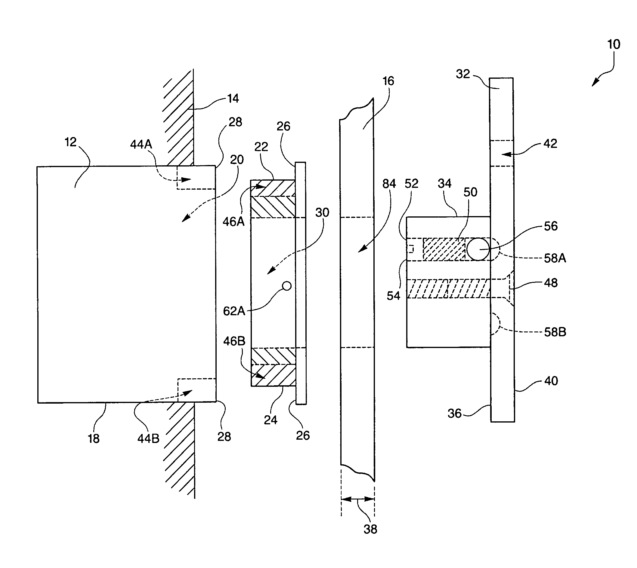
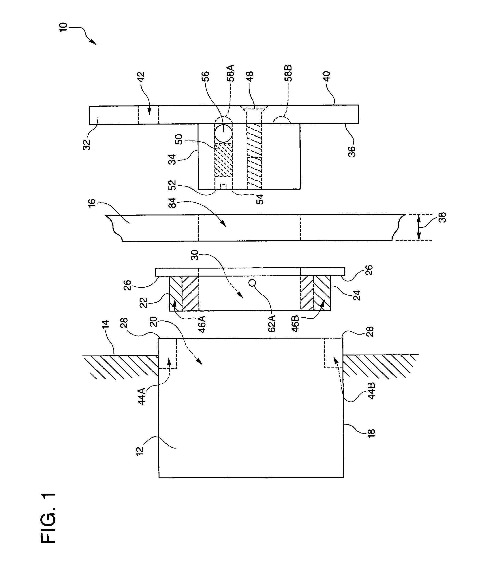
[0034]Referring to the drawing in detail, a cut-out tool for making a utility receptacle cut-out in sheeting material is shown in FIG. 1, and is generally represented by the reference numeral 10. As shown in FIG. 1, a utility receptacle, such as an electrical utility receptacle 12, is secured to a structural support 14 such as a strut 14 to which a section of sheeting material 16 is to be secured. The utility receptacle 12 includes a plurality of interconnected walls 18 that define a receptacle chamber 20 between the walls 18.

[0035]The cut-out tool includes an insert adaptor having a plurality of insert walls 24 configured to correspond with the plurality of interconnected walls 18 of the receptacle 12 so that the walls 24 of the insert adaptor 22 may be supported within the receptacle chamber 20 adjacent the receptacle walls 18. The insert adaptor 22 defines a mounting shoulder 26 that is secured to the insert walls 24 and is configured to overlie a perimeter edge 28 of the utility...


PUM


Abstract

The cut-out tool (10) includes an insert adaptor (22) configured to insert into and be secured within a utility receptacle (12) prior to sheeting material (16) overlying the receptacle (12), such as an electric receptacle (12). The insert adaptor (22) defines a mounting sleeve (30), and whenever the sheeting material (16) is secured over the receptacle (12) and insert (22), an insert hole (84) is cut adjacent and around an interior perimeter of the mounting sleeve (30). A mounting post (34) of an exterior template (32) is then secured within the mounting sleeve (30), and the exterior template (32) defines a cutting slot (42) that is dimensioned to contiguously and substantially overlie an exterior perimeter (28) of the receptacle (12). A cut is them made through the cutting slot (42) to define a template hole (86), and the sheeting material (16) then slides over the receptacle (12).

Description

CROSS REFERENCE TO RELATED APPLICATION[0001]This Application claims the benefit of U.S. Provisional Patent Application Ser. No. 61 / 000,045 that was filed on Oct. 23, 2007, entitled “Cut-Out Tool For Making A Utility Receptacle Cut-Out In Sheeting Material”.TECHNICAL FIELD[0002]The present invention relates to tools for facilitating making holes referred to as cut-outs in sheeting material such as “sheet rock” or “dry wall”, etc., and more particularly relates to a tool for efficiently making a precise cut-out around a utility receptacle.BACKGROUND ART[0003]It is known in the building field that constructing both residential and commercial structures involves erecting a frame of support structures or studs that define walls and ceilings, etc. Plumbing conduits and electrical lines are then passed along and through the studs, and the electrical lines typically extend into electrical receptacles that provide outlets, control switches, lighting fixture connections, etc. The electrical r...

Claims


Application Information

Patent Timeline
Patent Type & Authority Patents(United States)
IPC IPC(8): G01B1/00
CPCG01B3/14H02G1/00Y10S33/10
Inventor SHAPIRO, ALLAN
Owner SHAPIRO ALLAN
Why Eureka
Try Eureka