Compression ignition engine and exhaust system therefor

a compression ignition and engine technology, applied in electrical control, physical/chemical process catalysts, separation processes, etc., can solve the problems of increased hc and co emissions, sub-optimal active devices, and inability to train engineers

Inactive Publication Date: 2011-08-30
JOHNSON MATTHEY PLC
View PDF55 Cites 19 Cited by
  • Summary
  • Abstract
  • Description
  • Claims
  • Application Information

AI Technical Summary

Benefits of technology

[0023]An advantage of the present invention is that we have found that an exhaust system comprising both Pt and Pd is more effective at treating saturated and unsaturated HCs during normal running conditions, i.e. at exhaust gas temperatures wherein the Pt and / or Pd catalyst is above the light-off temperature for HC oxidation. Furthermore, when the temperature of the Pt catalyst is below its light-off temperature for catalysing the oxidation of HC, e.g. below about 250° C., the concentration of CO in the exhaust gas can be increased by switching to second mode operation so that an exotherm developed over the Pd catalyst can heat the Pt catalyst to above its HC light-off temperature. Indeed we believe that our results show a synergistic relationship exists in the combined use of Pd and Pt catalysts for treating compression ignition exhaust gases according to the present invention.
is that we have found that an exhaust system comprising both Pt and Pd is more effective at treating saturated and unsaturated HCs during normal running conditions, i.e. at exhaust gas temperatures wherein the Pt and / or Pd catalyst is above the light-off temperature for HC oxidation. Furthermore, when the temperature of the Pt catalyst is below its light-off temperature for catalysing the oxidation of HC, e.g. below about 250° C., the concentration of CO in the exhaust gas can be increased by switching to second mode operation so that an exotherm developed over the Pd catalyst can heat the Pt catalyst to above its HC light-off temperature. Indeed we believe that our results show a synergistic relationship exists in the combined use of Pd and Pt catalysts for treating compression ignition exhaust gases according to the present invention.

Problems solved by technology

However, as emission standards are tightened in forthcoming years, the challenge of the skilled engineer is how to meet them.
A problem with such devices is that when the exhaust gas temperature is too low e.g. during extensive periods of idling or slow driving conditions, the catalysts in the devices are sub-optimally active.
In the use of CSF, the filter can be regenerated actively by combusting injected HC fuel thereon in order to raise the filter temperature to about 600° C. However, unless the filter is above about 250-300° C. prior to HC injection, the HC may not be combusted on the filter or combustion may be incomplete, thus leading to increased HC and CO emissions.
A problem with prior art measures for increasing temperature in exhaust systems comprising DOC, the CRT®, CSF or NOx traps is that generally they result in an increased fuel penalty.

Method used

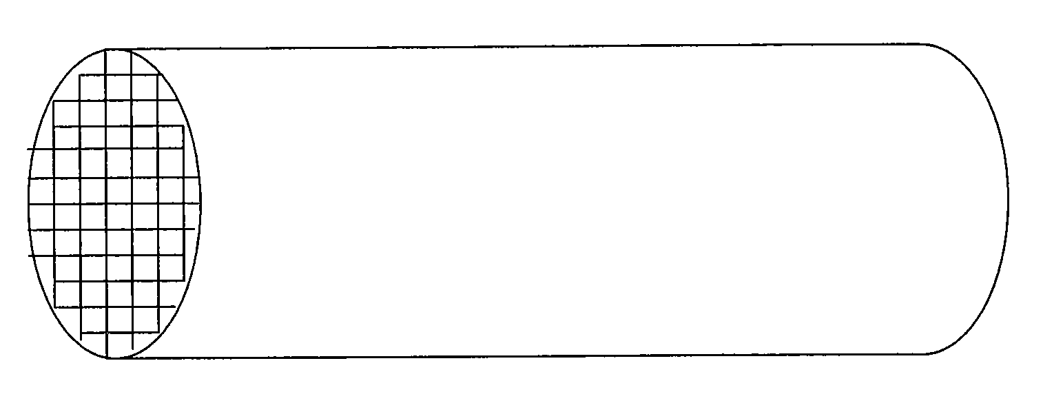
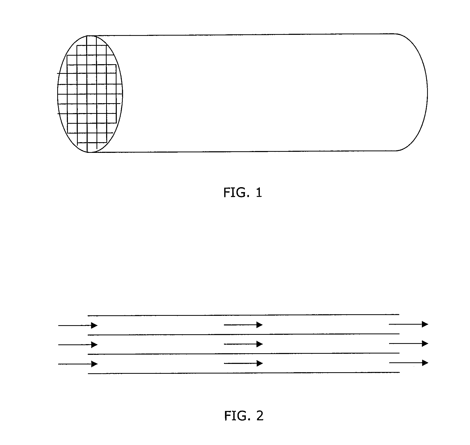

Image

  • Compression ignition engine and exhaust system therefor
  • Compression ignition engine and exhaust system therefor

Examples


example 1

[0063]A 2 wt % Pt-alumina-based catalyst (Catalyst A), a 2 wt % Pd-alumina-based catalyst (Catalyst B), and a 2 wt % Pd-ceria-containing catalyst (Catalyst C) were tested for HC and CO light-off in a simulated catalyst activity test (SCAT) gas rig. A sample of each catalyst was tested in the flowing gas mixtures set out in Table 1. The temperature of the gas mixtures used was increased during each test from 100° C. to 500° C.

[0064]

TABLE 1Gas mixtures used for activity tests for Catalysts A, B, and CGasGasGasGasMixture 1Mixture 2Mixture 3Mixture 4ppm HC (C1)60090030003000as propeneppm CO2006002500025000ppm NO200200200200% H2O4.54.54.54.5% O21212123% CO24.54.54.54.5ppm SO220202020N2BalanceBalanceBalanceBalanceFlow Rate300300300300(litres / hour / g sample)Ramp Rate10101010(° C. / min)

[0065]Gas mixtures 1 and 2 have HC and CO gas concentrations as typical of exhaust gases from a conventionally operated Diesel engine. Gas mixture 3 has higher HC and CO concentrations than gas mixtures 1 and 2...

example 2

[0070]In another series of activity tests, Catalyst D (1 wt % Pt-alumina-based), and Catalyst E (4 wt % Pd-ceria-based), were tested for HC and CO light-off in a SCAT gas rig using the gas mixtures set out in Table 4, and the temperature of the gas passed over each sample was increased during each test from 100° C. to 500° C.

[0071]

TABLE 4Gas mixtures used for activity tests of Catalysts D and E.GasGasGasGasGasMixture 5Mixture 6Mixture 7Mixture 8Mixture 9ppm HC600600600600600(C1) astolueneppm CO20095020001000025000ppm NO200200200200200% H2O4.54.54.54.54.5% O21212121212% CO24.54.54.54.54.5ppm SO22020202020N2BalanceBalanceBalanceBalanceBalanceFlow Rate300300300300300(litres / hour / g sample)Ramp Rate1010101010(° C. / min)

[0072]For each gas mixture from 5 to 9, the CO concentration was progressively increased and the remaining gases were kept constant with a nitrogen balance. Table 5 shows the effect of CO concentration on the HC and CO light-off of the catalysts.

[0073]

TABLE 5Temperature for...

example 3

[0075]Further SCAT rigs tests on Catalyst D (1 wt % Pt-alumina-based) and Catalyst E (4 wt % Pd-ceria-based) were carried out using the gas mixtures with 25000 ppm CO and two different HC concentrations (using either propene or toluene). A sample of each catalyst was placed in the gas mixtures shown in Table 6, and the temperature of the gas was increased from 100° C. to 500° C. The concentration of HC (as C1) was increased from 600 ppm to 3000 ppm using either propene or toluene as the HC species. The activity of the catalysts tested is given in Table 7.

[0076]

TABLE 6Gas mixtures used for activity tests on Catalyst A and Catalyst C.GasGasGasGasMixture 10Mixture 11Mixture 12Mixture 13ppm HC (C1)600300000as propeneppm HC (C1)006003000as tolueneppm CO25000250002500025000ppm NO200200200200% H2O4.54.54.54.5% O212121212% CO24.54.54.54.5ppm SO220202020N2BalanceBalanceBalanceBalanceFlow Rate300300300300(litres / hour / g sample)Ramp Rate10101010(° C. / min)

[0077]

TABLE 7Temperature for 80% convers...


PUM

PropertyMeasurementUnit
temperatureaaaaaaaaaa

Abstract

A system including a compression ignition engine operable in a first, normal running mode and operable in a second mode to produce an exhaust gas having an increased level of carbon monoxide (CO) relative to the exhaust gas produced in the first mode. The system, when in use, can switch engine operation between the two modes, and the system includes an exhaust system. The exhaust system includes a supported palladium (Pd) catalyst associated with at least one base metal promoter and an optionally supported platinum (Pt) catalyst associated with and / or downstream of the Pd catalyst wherein CO is oxidised by the supported Pd catalyst during second mode operation.

Description

[0001]This application is the U.S. national phase application of PCT International Application No. PCT / GB2003 / 004002, filed Sep. 15, 2003, and claims priority of British Patent Application No. 0221228.0, filed Sep. 13, 2002, and British Patent Application No. 0303660.5, filed Feb. 18, 2003.[0002]The present invention relates to a compression ignition engine, such as a diesel engine, and an exhaust system therefor.BACKGROUND OF THE INVENTION[0003]Conventional compression ignition engines, such as diesel engines, produce less gaseous hydrocarbon (HC) and carbon monoxide (CO) than gasoline engines and it is possible to meet present legislated limits for these components using a platinum (Pt)-based diesel oxidation catalyst (DOC) disposed on a flow through honeycomb monolith. Diesel nitrogen oxide (NOx) emissions are presently controlled by engine management, such as exhaust gas recirculation (EGR). As a consequence, however, diesel particulate matter (PM) emissions including volatile a...

Claims


Application Information

Patent Timeline
Patent Type & Authority Patents(United States)
IPC IPC(8): F01N3/00F02D43/00B01D53/86B01D53/94B01J23/42B01J23/44B01J23/58B01J23/63B01J23/656F01N3/02F01N3/035F01N3/08F01N3/10F01N3/20F01N3/24F01N3/28F01N13/02F02B3/06F02D21/08F02D41/02
CPCB01D53/945F01N13/0097B01D53/9495F01N3/035F01N3/0814F01N3/0821F01N3/20F01N3/206F01N3/2803F02D41/027F01N13/009B01D2255/1021B01D2255/1023B01D2255/9155B01J23/42B01J23/44B01J23/63B01J23/6562F01N2370/04F02B3/06Y02T10/22B01D53/9472Y02A50/20Y02T10/12F01N3/28F02B1/12
Inventor TWIGG, MARTYN VINCENTPHILLIPS, PAUL RICHARD
Owner JOHNSON MATTHEY PLC
Why Eureka
Try Eureka