Transporting particulate material

a technology for transporting particulates and parts, applied in the direction of transportation and packaging, machines/engines, containers, etc., can solve the problems of dust handling, maintenance, wear on components, and significant problems affecting the efficiency of use costs, so as to reduce the passage of dust

Inactive Publication Date: 2011-08-30
AIR PROD & CHEM INC
View PDF25 Cites 22 Cited by
  • Summary
  • Abstract
  • Description
  • Claims
  • Application Information

AI Technical Summary

Benefits of technology

[0014]A yet further aspect of the invention provides the at least one rotary transporting apparatus comprising a transport duct having an inlet and an outlet downstream of the inlet, and a primary transport channel located between the inlet and the outlet, the primary transport channel being defined by a pair of opposed moving surfaces which move between the inlet and the outlet towards the outlet, at least one of the moving surfaces having a series of discontinuities, each of the discontinuities configured to define a transport facilitation zone contiguous with the primary transport channel such that material within the transport facilitation zone is contiguous with material within the primary transport channel, each of the discontinuities having a downstream facing drive surface; and motive means for moving the movable surfaces between the inlet and the outlet towards the outlet; and at least one seal to reduce the passage of dust and debris from the material transporting apparatus hopper structure, while allowing the at least one rotary transporting apparatus to rotate relative to material transporting apparatus hopper structure.

Problems solved by technology

Industrial and commercial scale operations of such transporting and / or metering apparatuses can result in significant issues relating to efficiency in usage costs, maintenance, wear on components and dust handling.

Method used


Image

  • Transporting particulate material
  • Transporting particulate material
  • Transporting particulate material

Examples


Embodiment Construction

[0050]The following detailed description is of the best presently contemplated mode of carrying out the invention. This description is not to be taken in a limiting sense, but is made merely for the purpose of illustrating general principles of embodiments of the invention.

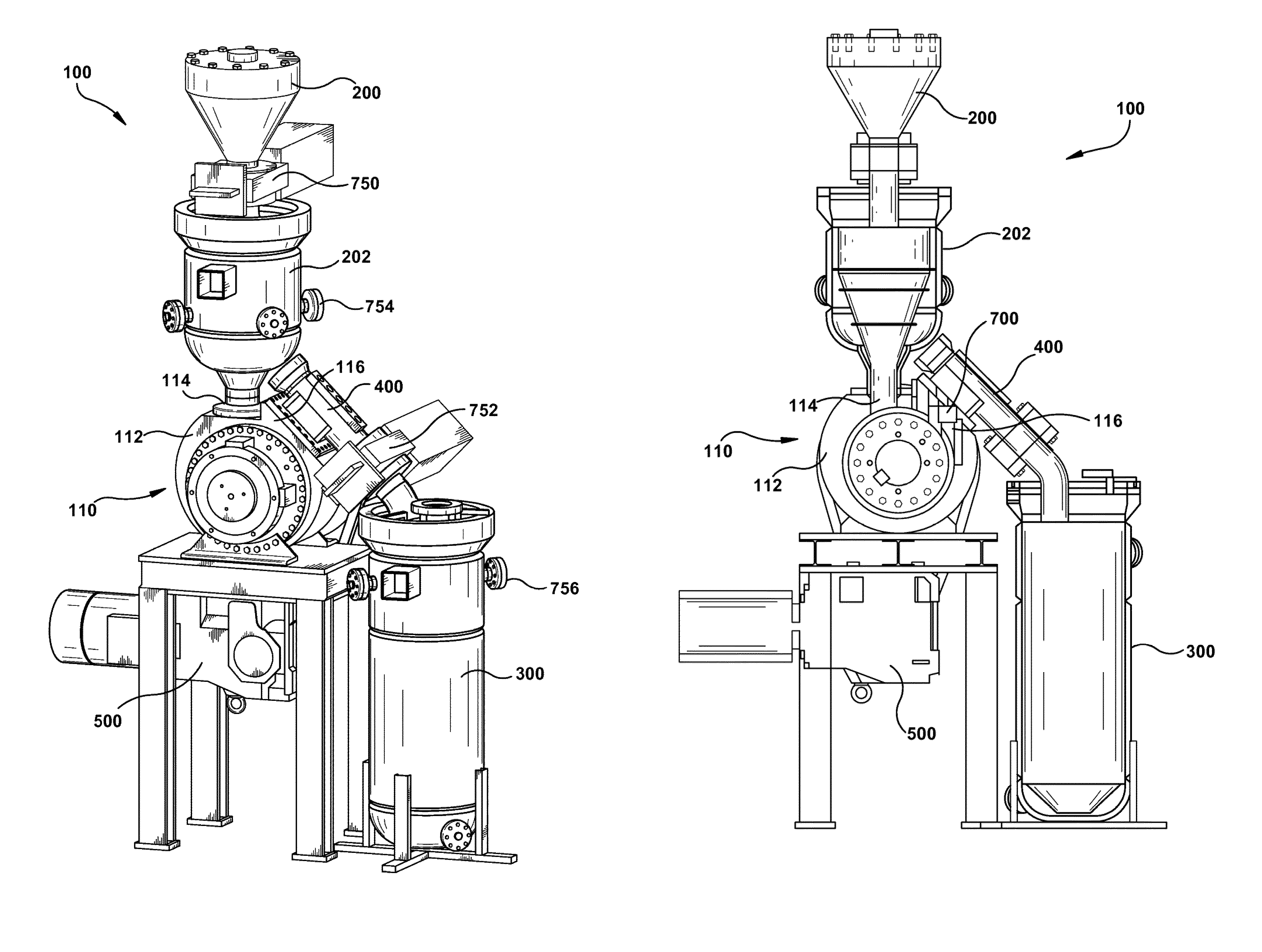
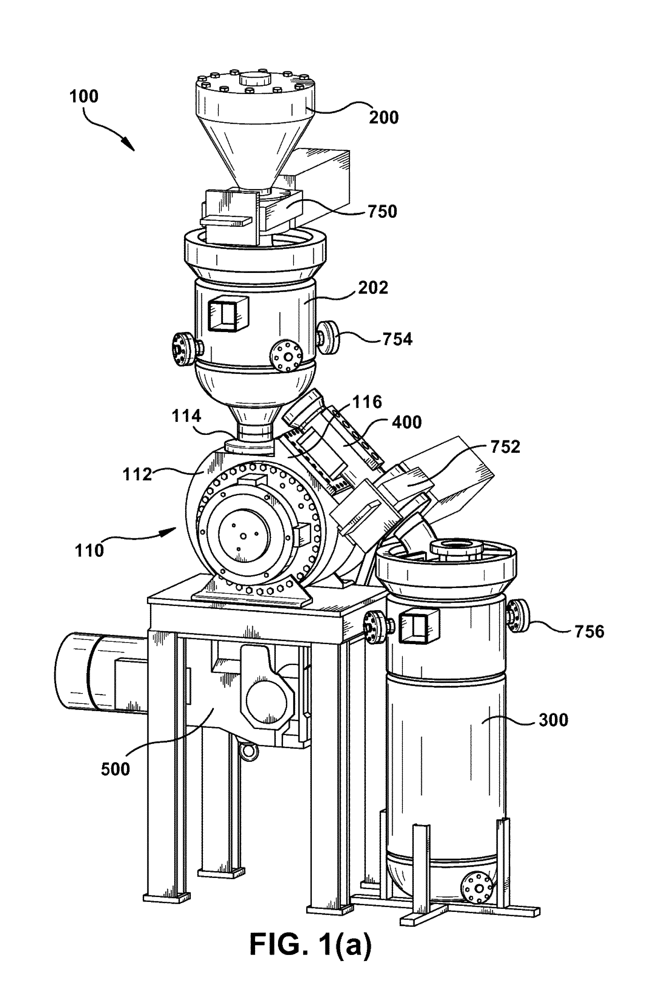
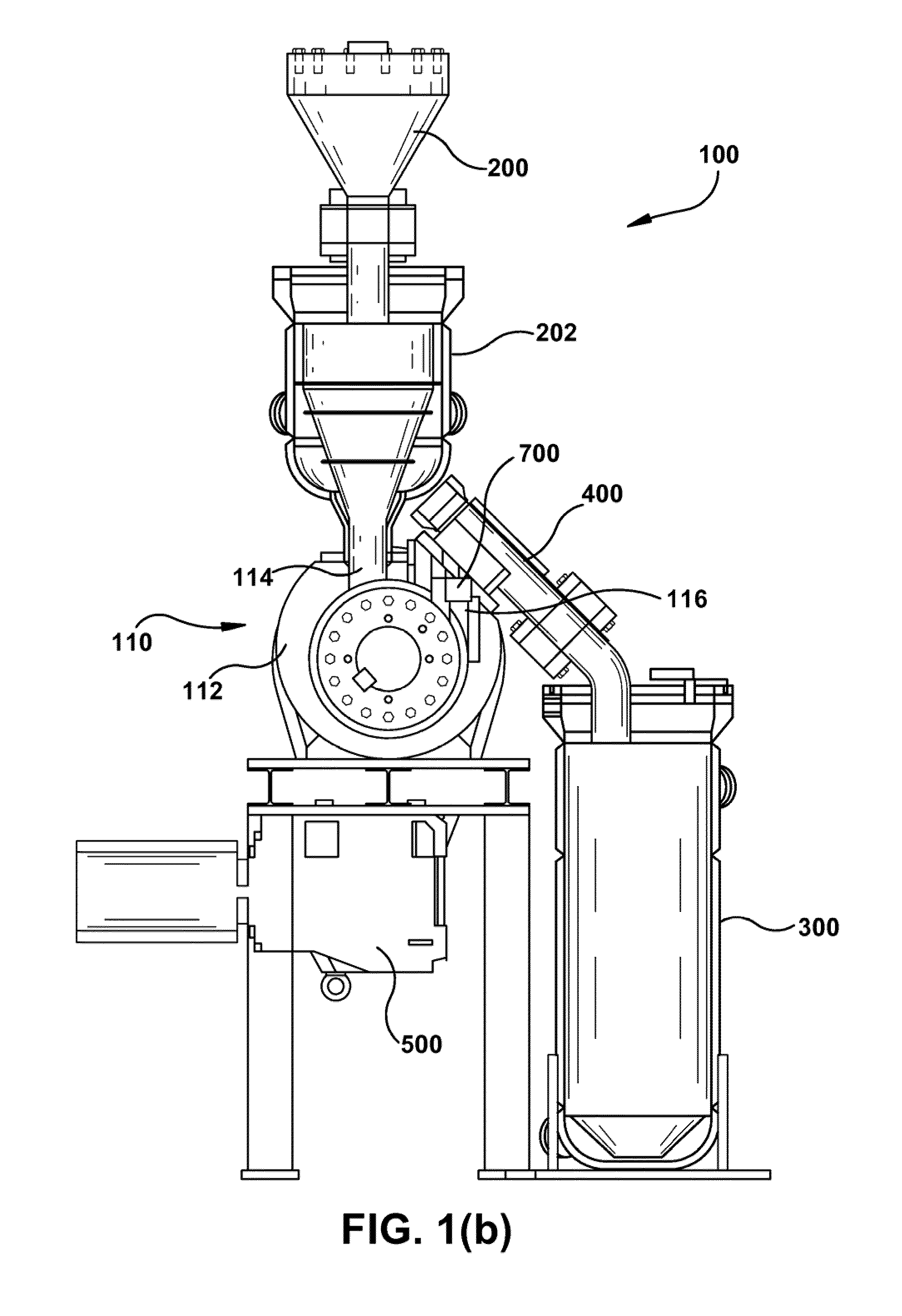
[0051]The invention relates generally to systems, apparatuses and methods for transporting and metering particulate material. Particular embodiments of the invention relate to apparatuses that employ general rotary disk principles such, but not limited to those described in, for example, one or more of U.S. Pat. Nos. 5,355,993, 5,381,886, 5,402,876 and 6,213,289.

[0052]A prior art apparatus 10 for transporting particulate material similar to the embodiment of FIGS. 1-3 of the U.S. Pat. No. 5,402,876 and FIGS. 1-3 of U.S. Pat. No. 5,355,993 is illustrated in FIGS. 22-24 herein. Corresponding reference numbers are used herein, for convenience. FIG. 22 is a partial cross-sectional view of a disk type transporting appa...


PUM


Abstract

A material transporting system comprises a material transporting apparatus (100) including a material transporting apparatus hopper structure (200, 202), which comprises at least one rotary transporting apparatus; a stationary hub structure (900) constraining and assisting the at least one rotary transporting apparatus; an outlet duct configuration (700) configured to permit material to exit therefrom and comprising at least one diverging portion (702, 702′); an outlet abutment configuration (800) configured to direct material to the outlet duct configuration; an outlet valve assembly from the material transporting system venting the material transporting system; and a moving wall configuration in the material transporting apparatus capable of assisting the material transporting apparatus in transporting material in the material transporting system. Material can be moved from the material transporting apparatus hopper structure to the outlet duct configuration through the at least one rotary transporting apparatus, the outlet abutment configuration, and the outlet valve assembly.

Description

CROSS-REFERENCE TO RELATED APPLICATIONS[0001]This is a continuation of PCT patent application number PCT / US2008 / 060593, filed on Apr. 17, 2008, which claims priority to U.S. provisional patent application Ser. No. 60 / 925,366, filed on Apr. 20, 2007, and U.S. provisional patent application Ser. No. 60 / 942,418, filed on Jun. 6, 2007, each of which is incorporated herein by reference in its entirety.STATEMENT REGARDING FEDERALLY SPONSORED RESEARCH OR DEVELOPMENT[0002]This invention was made with Government support under cooperative agreement under the authority of Public Law 95-91 DOE Organization Act, and P. L. 95-224 Federal Grant and cooperative Agreement Act as amended by P. L. 97-258 (Instrument No. DE-FC26-02NT41439) awarded by the United States Department of Energy. The Government may have certain rights in the invention.BACKGROUND OF THE INVENTION[0003]The invention relates, generally, to systems and apparatuses for transporting particulate material, components of such systems ...

Claims


Application Information

Patent Timeline
Patent Type & Authority Patents(United States)
IPC IPC(8): B65G31/00
CPCB65D88/66B65G53/46
Inventor ALDRED, DEREK LESLIERADER, JEFFREY A.SAUNDERS, TIMOTHY W.
Owner AIR PROD & CHEM INC
Why Eureka
Try Eureka