Scroll fluid machine having a coupling mechanism to allow relative orbiting movement of scrolls

a scroll fluid machine and scroll technology, applied in couplings, machines/engines, liquid fuel engines, etc., can solve the problems of increasing manufacturing costs, increasing clearance, and producing vibration and noise, so as to reduce the power for driving and reduce the noise

Inactive Publication Date: 2011-08-30
ANEST IWATA CORP
View PDF13 Cites 18 Cited by
  • Summary
  • Abstract
  • Description
  • Claims
  • Application Information

AI Technical Summary

Benefits of technology

[0023]According to the invention, the first scroll and the second scroll is connected by a plate spring member or members surrounding the scroll laps of both the scrolls with a face of the plate spring member or members facing radially inwardly so that relative movement between the first and second scrolls is possible in a plane perpendicular to the rotation axes of both scrolls, the center axes of both the scrolls are offset from each other so that relative revolving motion is produced between both the scrolls, so the relative revolving can be achieved without incorporating the Oldham coupling or pin crank mechanism which includes sliding parts. Therefore, a scroll fluid machine can be provided which requires no lubrication for anti-rotation mechanism making it maintenance-free, reduced in power for driving due to elimination of sliding parts, and decreased in noise due to absence of clearances of sliding parts.
[0035]Two groups of arcuate plate springs each consisting of four arcuate plate springs can be used to connect the first scroll to the second scroll by fixing an end of an arcuate plate spring to a first support flange of the first scroll and fixing the other end of said arcuate plate spring to a second support flange of the second scroll so that the first support flanges provided to the first scroll at equal circumferential spacing and the second support flanges provided to the second scroll at equal circumferential spacing are connected by arcuate plate springs one after the other in two rows in axial direction. When torque is transmitted from the first scroll to the second scroll so that tension stress is produced in one of the groups of arcuate plate springs belonging to a row, compression stress is produced in the other group of the arcuate plate springs belonging to the other row. Therefore, occurrence of torsion of the first scroll relative to the second scroll can be effectively prevented, and stable revolving of the revolving scroll or relative revolving motion between the both the scrolls can be achieved.

Problems solved by technology

In an Oldham coupling type anti-rotation mechanism, grooves and rectangular protrusions to be received in the grooves are formed as shown in FIG. 9, so abrasion of the grooves and rectangular protrusions tend to occur resulting in increased clearance therebetween, which produces vibration and noise.
In a scroll fluid machine adopting pin crank type anti-rotation mechanism as shown in FIGS. 11a, 11b, usually three pin cranks are provided, and angular contact ball bearings are used to maintain proper clearance between the top faces of the scroll laps and the mating mirror surfaces of the stationary and revolving scrolls, structure becomes complicated resulting in increased manufacturing cost.
Further, the bearings of the pin cranks must be lubricated by lubrication oil or grease, controlling of temperature of the bearings is necessary, and there remains a problem that noise increases due to wear of the bearings.
In either case of adopting as anti-rotation mechanism the Oldham coupling mechanism or pin crank mechanism, it is necessary to supply lubrication oil and take measure against abrasion, so it is difficult to provide an oil-free scroll fluid machine.
Even if the anti-rotation mechanism is composed of self-lubricating material, to completely solve the problem of increase in clearances is difficult as long as sliding parts exist in the mechanism.
Even if oil-free construction is realized in the compression rooms formed by the scroll laps, there remains fear that lubrication oil or grease for lubricating the anti-rotation mechanism intrudes into the compression rooms of the scroll compressor.

Method used


Image

  • Scroll fluid machine having a coupling mechanism to allow relative orbiting movement of scrolls
  • Scroll fluid machine having a coupling mechanism to allow relative orbiting movement of scrolls
  • Scroll fluid machine having a coupling mechanism to allow relative orbiting movement of scrolls

Examples


first embodiment

[0058]the scroll fluid machine utilizing the shaft coupling mechanism mentioned above will be explained referring to FIGS. 5 and 6.

[0059]Referring to FIG. 5, a scroll compressor 50 comprises a revolving scroll 52 having a revolving scroll lap 54, a stationary scroll 58 having a stationary scroll lap 56, a scroll casing 60 fixed to the stationary scroll 58 and covering the revolving scroll 52, a motor casing 64 of a motor 62 for driving the revolving scroll 52.

[0060]A discharge port 68 and a discharge opening 70 communicating to the discharge port 68 are provided to the stationary scroll 58 at the center of the stationary scroll plate of which the inside surface is finished to a mirror surface 58a. The stationary scroll lap 56 erects from the mirror surface 58a extending spirally outward from near the periphery of the discharge port 68. A tip seal (not shown) made of self-lubricating material is received in a tip seal groove (not shown) of the stationary scroll lap 56. The stationary...

second embodiment

[0080]Next, scroll fluid machine applying the anti-rotation mechanism will be explained referring to FIG. 7.

[0081]The scroll compressor 200 of the second embodiment is a so-called full-rotation type scroll compressor. The full-rotation type scroll compressor comprises a drive scroll and a driven scroll of which the rotation axis is offset from that of the drive scroll, the driven scroll is driven by the spiraling scroll lap of the drive scroll meshing with that of the driven scroll, and relative revolving motion is produced between the scroll laps of both scrolls. In FIG. 7, constituent parts the same as those of the scroll compressor 50 of FIG. 5 is denoted by the same reference numerals and explanation will be omitted.

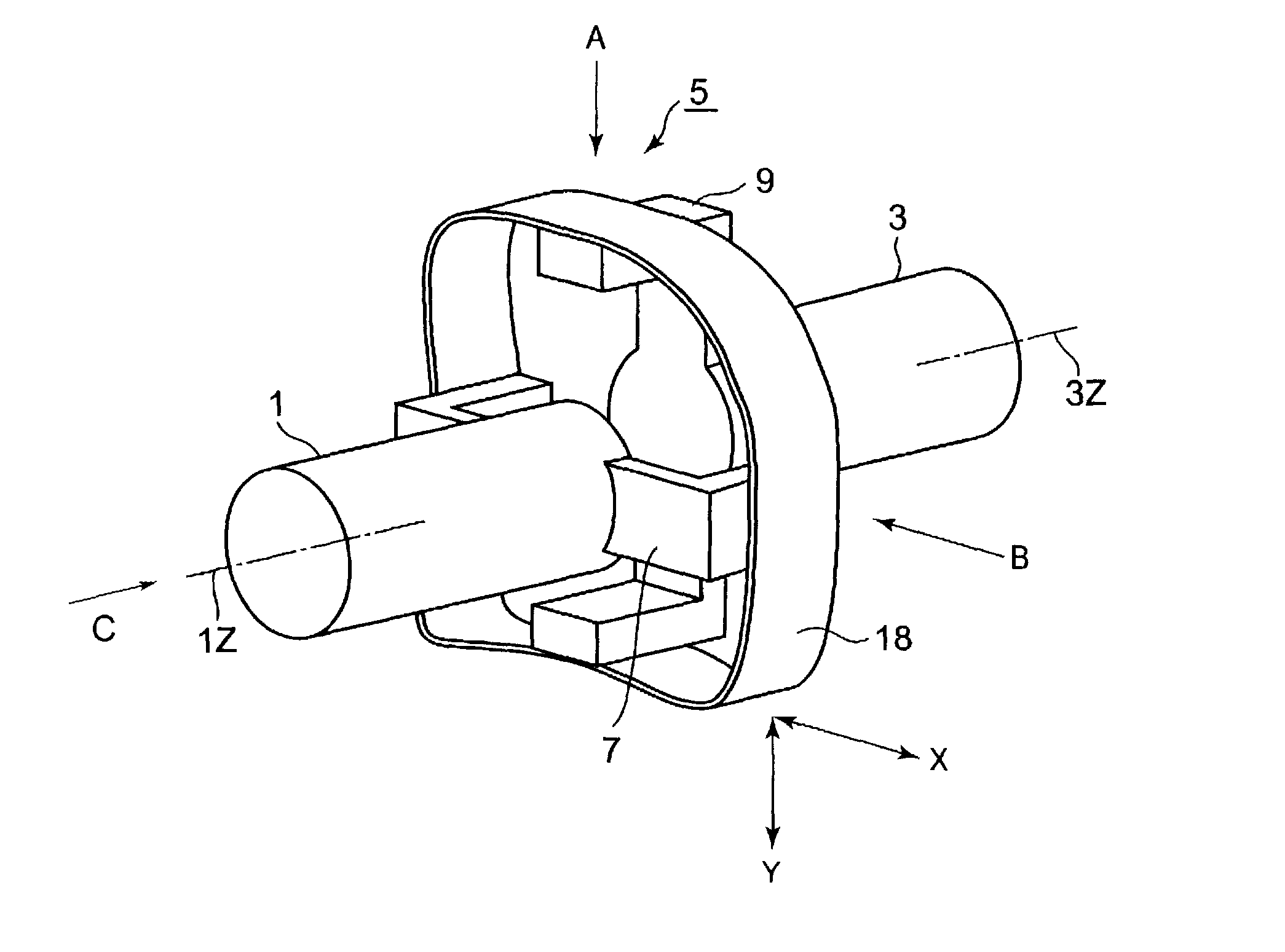
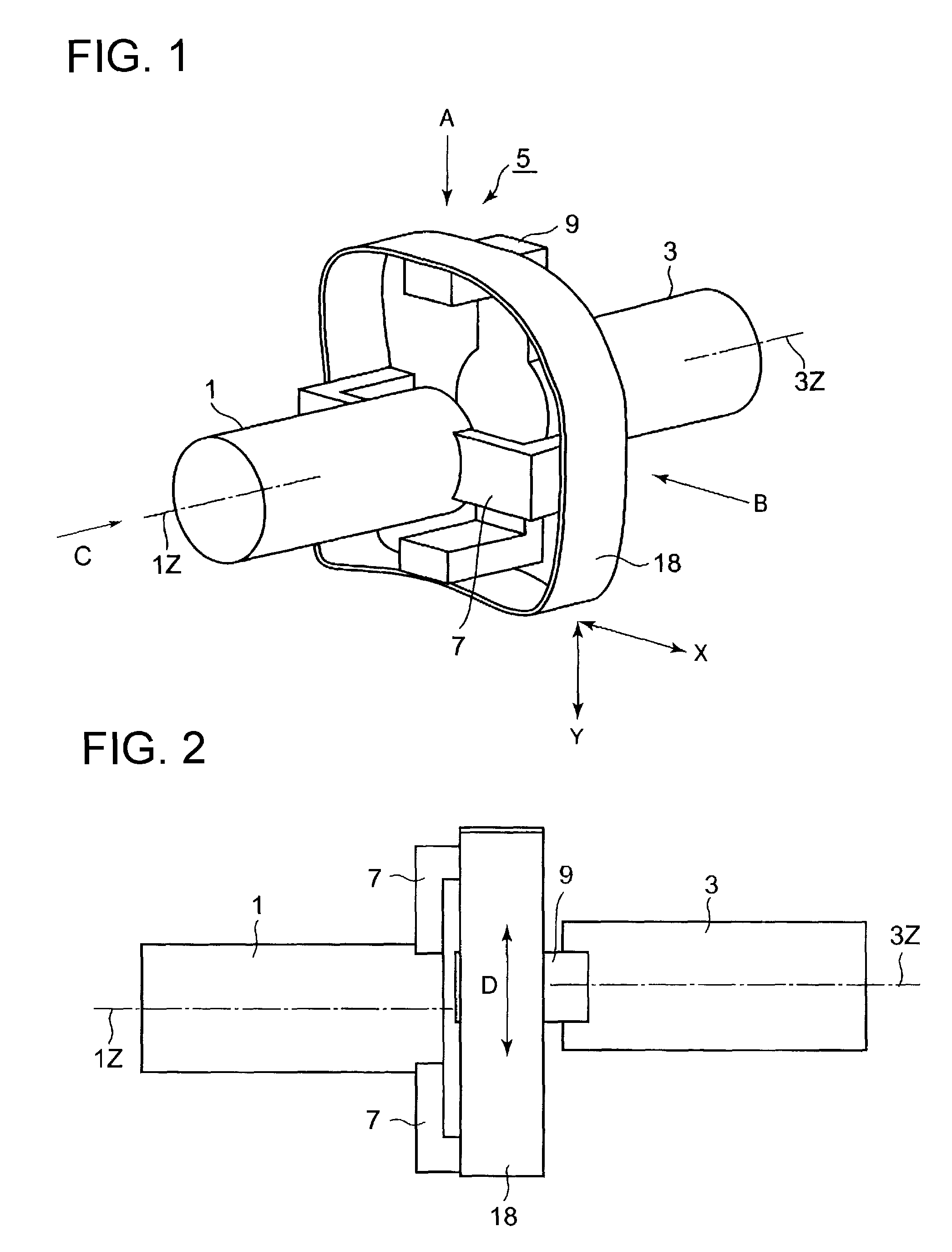
[0082]Again referring to FIG. 1, when the main shaft 1 and follower shaft 3 are supported for rotation respectively with an eccentricity of d between the rotation axes 1Z and 3Z, rotation of the main shaft 1 is transmitted to the follower shaft 3 via the annular plat...


PUM


Abstract

A scroll fluid machine has a stationary scroll having a stationary scroll lap fixed to a scroll casing and an orbiting scroll having an orbiting scroll lap that orbits relative to the stationary scroll lap. The stationary and orbiting scrolls are connected via a coupling mechanism other than an Oldham coupling or pin crank type mechanism having sliding parts. The coupling mechanism includes plate springs that connect the stationary scroll to the orbiting scroll. The orbiting scroll lap engages with the stationary scroll lap to form a closed compression chamber.

Description

TECHNICAL FIELD[0001]The present invention relates to a scroll fluid machine for compressing fluid, specifically relates to a mechanism for revolving the revolving scroll of the scroll fluid machine.BACKGROUND ART[0002]Rotation prevention mechanism for preventing rotation of the revolving scroll and defining the radius of revolution thereof such as a crank mechanism and Oldham coupling has been adopted in scroll fluid machines.[0003]First, the principle of scroll compressor will be explained briefly with reference to FIGS. 8a to 8d. [0004]A scroll compressor consists of a stationary scroll having a spiraling scroll lap 011 and a revolving scroll having a spiral lap 013. Gas ingested from an inlet port 017 is compressed as a revolving scroll revolves and the compressed gas is discharged from a discharge port 025 at the center. A stationary scroll lap 011 is formed on a disk fixed perpendicular to a rotation shaft. The revolving scroll lap 013 and the stationary scroll lap 011 spiral ...

Claims


Application Information

Patent Timeline
Patent Type & Authority Patents(United States)
IPC IPC(8): F03C4/00F04C18/00
CPCF04C18/0215F04C29/0057F04C18/02
Inventor YANAGISAWA, KEN
Owner ANEST IWATA CORP
Why Eureka
Try Eureka