Determination of gas flux using airborne dial lidar

a dial lidar and gas flux technology, applied in the field of spectroscopic analysis, can solve the problem of making the measurement of emissions from these types of sites more difficul

Active Publication Date: 2011-08-30
HARRIS CORP
View PDF27 Cites 25 Cited by
  • Summary
  • Abstract
  • Description
  • Claims
  • Application Information

AI Technical Summary

Problems solved by technology

Measuring the emissions from these types of sites is made more diffi

Method used


Image

  • Determination of gas flux using airborne dial lidar
  • Determination of gas flux using airborne dial lidar
  • Determination of gas flux using airborne dial lidar

Examples


example

(4)

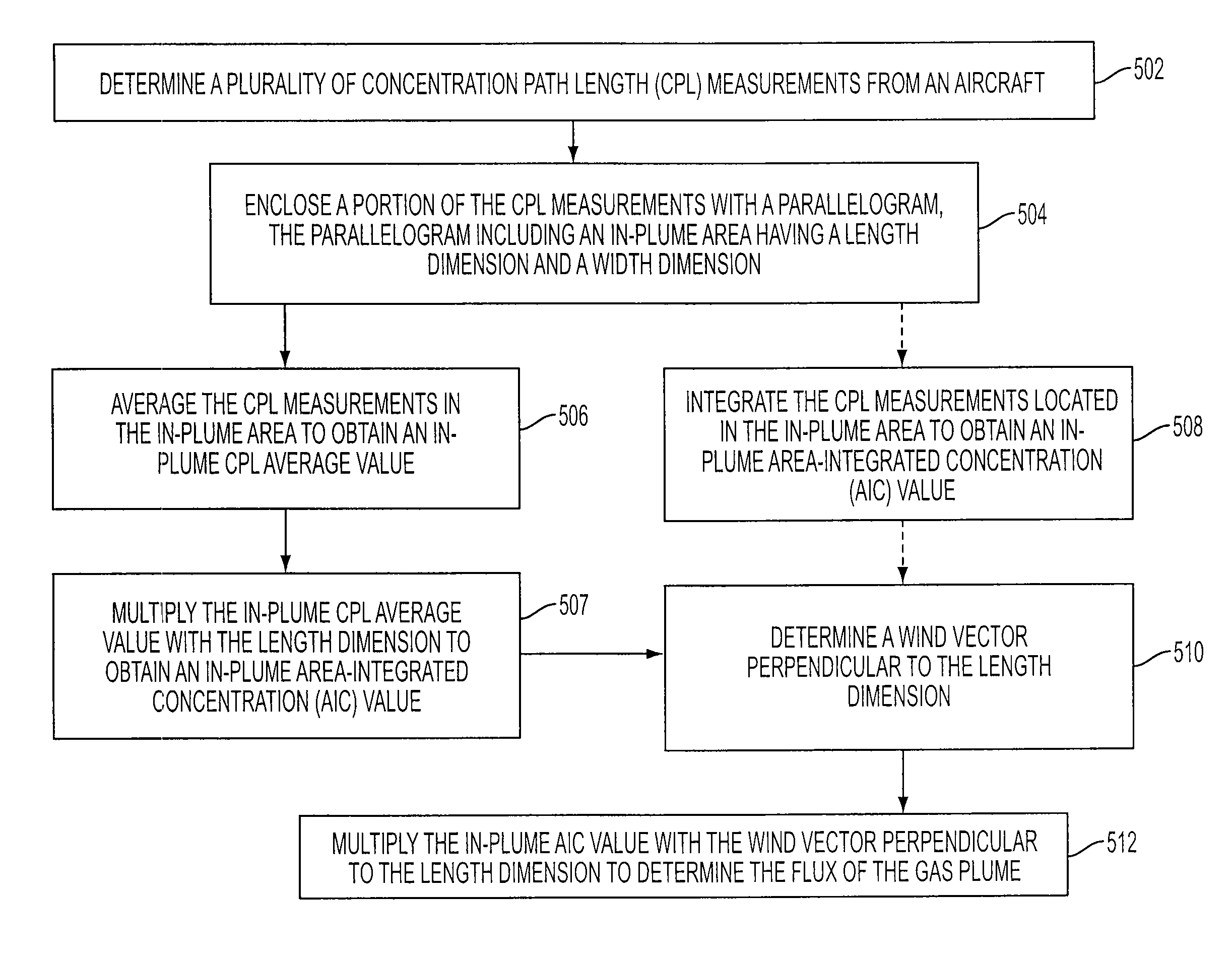
Process for Determining Methane Release Rate Using Software

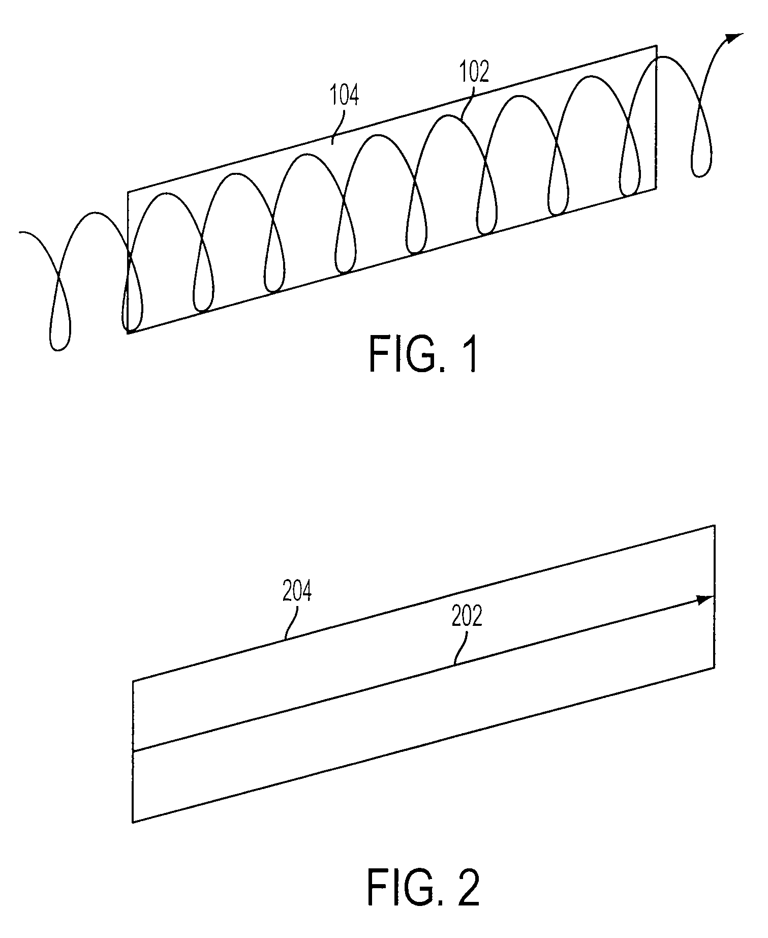
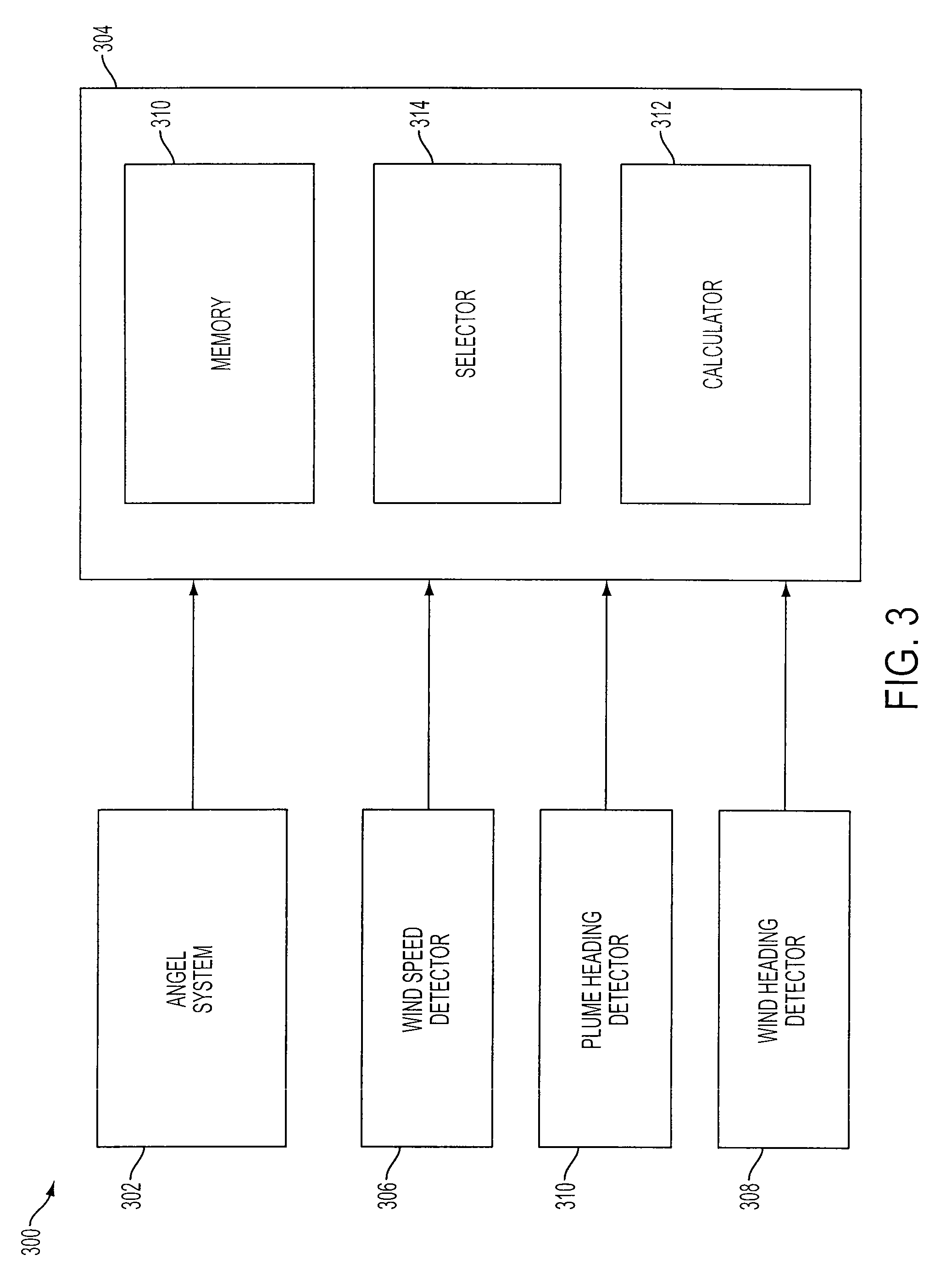
[0062]According to an exemplary embodiment of the invention, software may be used to determine methane flux. Calculator 312, shown at FIG. 3, may be used to execute the software. This example utilizes data processed from the ANGEL system flown at approximately 220 m AGL, to provide ground geolocated, CPL values at a measurement rate of 1 kHz. Thus, for an aircraft flying at 120 mph, the CPL measurements are an average of 0.056 m (5.6 cm) apart in the flight direction. The ANGEL system illuminates a ground spot of approximately 1 m diameter so adjacent measurements are overlapped.

[0063]Because of the overlapping measurements, high spatial density is not required but is useful for data averaging purposes in order to improve accuracy. The data may be output in different formats. This example uses output produced in ESRI ArcMap format, along with an ArcMap program. Other programs may also be used. For example, the determinati...


PUM


Abstract

A system is provided for determining emission rate of a gas from a source. The system includes a selector for designating an in-plume area extending across a plume of gas. The in-plume area includes a length dimension greater than a width dimension. The system also includes a processor for determining an area-integrated concentration value for the in-plume area. The system further includes a wind vector received by the processor. The processor determines the emission rate of the gas based on the area-integrated concentration value and a vector component of the wind vector.

Description

FIELD OF THE INVENTION[0001]The invention relates generally to the field of spectroscopic analysis. More specifically, the invention relates to a spectroscopic analysis of gases emanating from natural gas and oil pipelines and determination of gas flux using laser differential absorption, wind speed and wind direction.BACKGROUND OF THE INVENTION[0002]Technologies available for the rate quantification of gas(es) emitted from a point source such as a smokestack or a leaking pipeline are numerous and well understood. These techniques include use of rotameters or hot-wire anemometers to measure the velocity of gasses escaping from a hole of known size. Also included are more high tech devices like the Hi-Flow sampler which is an instrument that combines a hydrocarbon detector with a flowmeter and vacuum system.[0003]Measurement of emission flux from larger, more complex non-point sources of emissions may be accomplished by numerical calculations within the facility (for example, estimat...

Claims


Application Information

Patent Timeline
IPC IPC(8): G01S17/00
CPCG01S17/95Y02A90/10
Inventor STEARNS, STEVEN VINCENTLIPPERT, JOSEPH LAWRENCE
Owner HARRIS CORP
Why Eureka
Try Eureka