
Drilling system and methods of drilling lateral boreholes

a drilling system and lateral borehole technology, applied in the direction of directional drilling, artificial islands, foundation engineering, etc., can solve the problems of limited vertical extent, slow and expensive process, and relatively complex mechanism for connecting the kick plate to the drilling machine and orienting it to drill in the desired direction

Active Publication Date: 2011-09-06
SCHLUMBERGER TECH CORP
View PDF12 Cites 7 Cited by
  • Summary
  • Abstract
  • Description
  • Claims
  • Application Information

AI Technical Summary

Benefits of technology

The invention is a drilling system that allows for the efficient and accurate drilling of multiple lateral boreholes from a main borehole. The system includes a drilling machine, a drill string, a guide, and sensors. The guide is connected to the drilling machine and can be positioned in the main borehole to direct the drill string in a radial direction. The drill string is then driven in an axial direction, resulting in the drill bit engaging the guide and the guide deflecting the drill string in a predetermined direction. The guide can be anchored in place to secure it in the borehole. The system also includes a telescopic link and a control line for easy positioning and operation. The invention provides a convenient and efficient solution for drilling multiple lateral boreholes.

Problems solved by technology

Such formations often have significant horizontal extent but are of limited vertical extent.
However, in certain cases, only a ‘vertical’ borehole is available.
Thus the process is slow and expensing, as it requires the presence of a drilling rig or a coiled tubing drilling unit to perform these operations.
The mechanism for connecting the kick plate to the drilling machine and for orienting it to drill in the desired direction is relatively complex.

Method used


Image

  • Drilling system and methods of drilling lateral boreholes
  • Drilling system and methods of drilling lateral boreholes
  • Drilling system and methods of drilling lateral boreholes

Examples


first embodiment

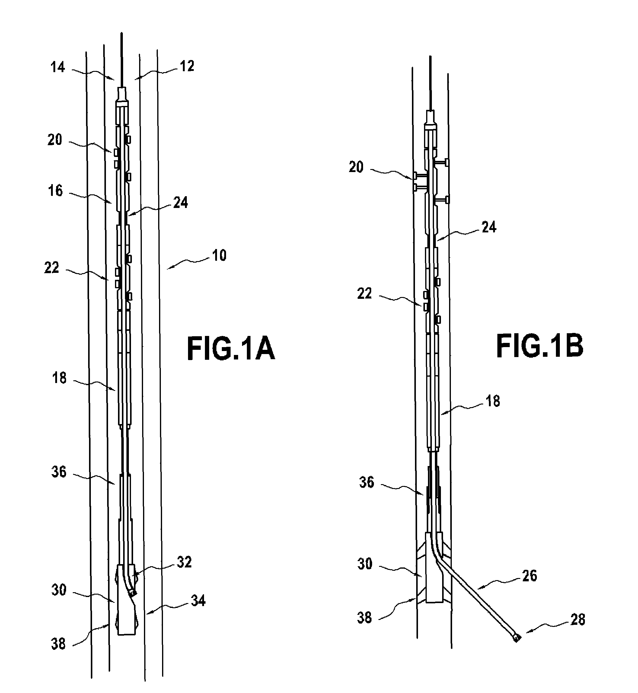
[0037]the invention is shown in FIGS. 1a and 1b. The drilling system shown therein comprises a drilling machine 10 suspended in a main borehole 12 on a wireline cable 14 that extends to the surface.

[0038]The drilling machine 10 comprises a drilling tractor 16 and a drilling motor 18. The drilling tractor 16 is preferably of the type described in WO 2004072437 A and includes pairs of anchors 20, 22 and a drive section 24. By sequentially deploying the anchors 20, 22 and operating the drive section 24 to extend and contract, the drilling tractor 16 can be caused to move along the main borehole 12 and apply an axial driving force to any equipment connected thereto.

[0039]The drilling motor 18 is connected to the lower end of drilling tractor 16 and provides a rotary drive relative to the tractor 16. Appropriate sensors are included to establish the rotary position of the motor output in the borehole allowing operation of the motor 18 to achieve any predetermined orientation. Such sensor...

second embodiment

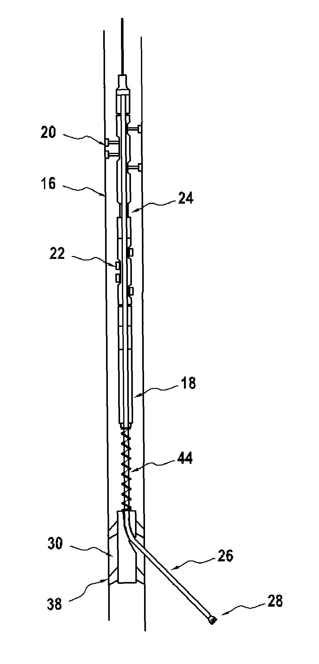
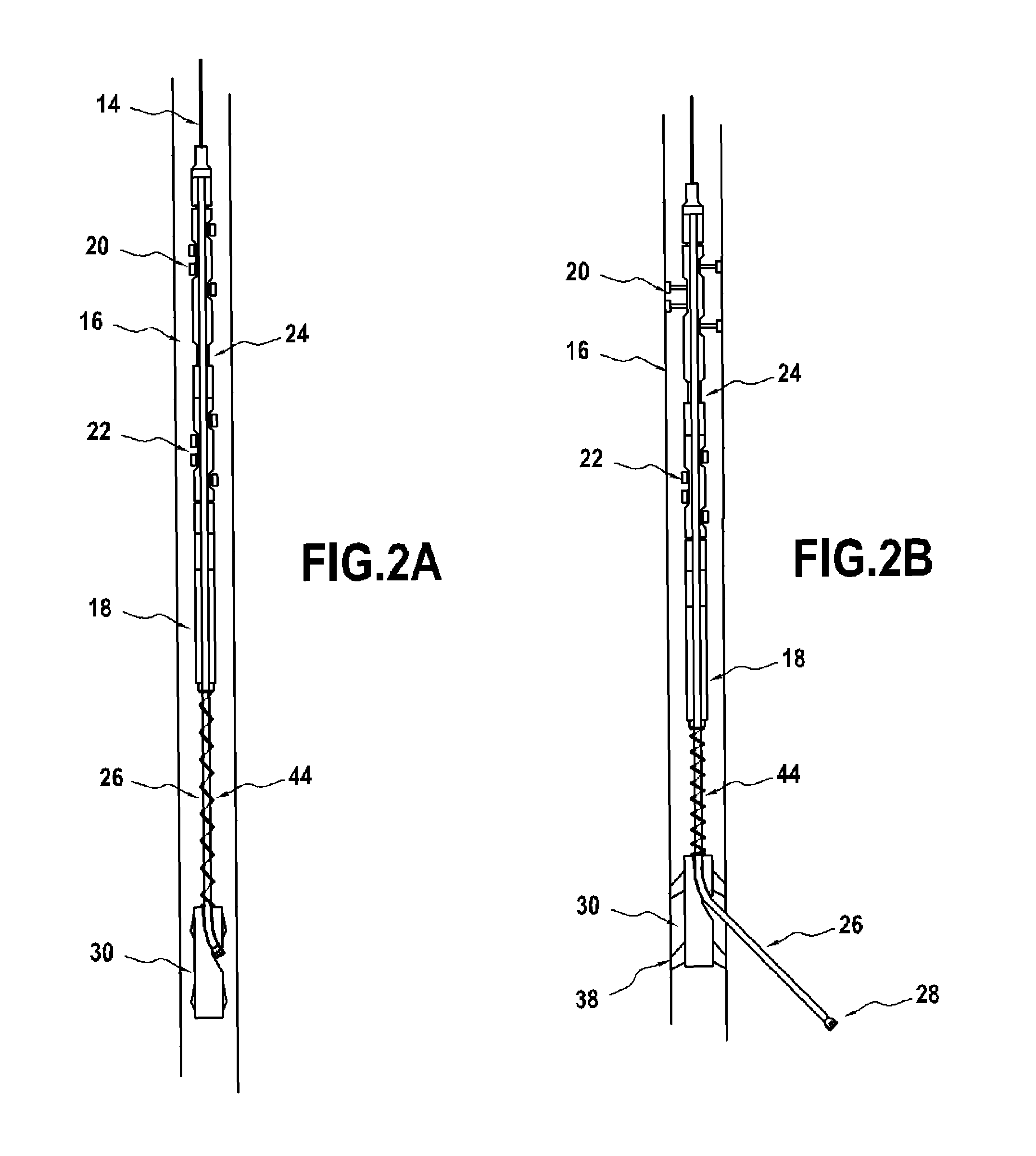
[0046]FIGS. 2a and 2b show corresponding views of a system according to the invention. The same reference numerals are used as in FIGS. 1a and 1b for the same parts. The embodiment of FIGS. 2a and 2b differs from that of FIGS. 1a and 1b in that there is no telescopic support. In this embodiment, the drilling machine 10 supports the weight of the guide 30 using the drill string 26. This is achieved using a shaped seat 40 in the exit to the guide path 32 into which the drill bit seats (see FIG. 3), or by providing a contact ring 42 at the end of the drill string 26 adjacent the drill bit 28, the contact ring sitting in the seat 40 (see FIG. 4). The drill string 26 has a key formation 41 adjacent the drill bit 28 that sits in a recess 43 in the exit to the guide path 32 (see FIG. 5). The engagement of the key 41 in the recess 43 means that the drill string 26 cannot rotate relative to the guide 30. Therefore, rotation of the drill string 26 using the drilling motor 18 can be used to or...


PUM


Abstract

A drilling system is presented for use in drilling lateral boreholes from a main borehole. The drilling system generally comprises a drilling machine, a drill string connected to the drilling machine so as to be driveable in an axial direction, and a guide connected to the drilling machine such that when the drill string is driven axially by the drilling machine, it interacts with the guide so as to be directed in a predetermined radial direction. A method of drilling a lateral borehole from a main borehole is also presented, comprising the steps of: positioning the drilling system in the main borehole; anchoring the guide in the borehole; operating the drilling machine to drive the drill string in an axial direction; and deflecting the drill string, by means of the guide, in a radial direction into the wall of the main borehole to drill the lateral borehole.

Description

TECHNICAL FIELD[0001]This invention relates to drilling systems and in particular to such systems for use in drilling lateral boreholes from a main borehole.BACKGROUND ART[0002]In the extraction of hydrocarbons such as oil and gas from underground formations, it is common practice to drill a borehole from the surface to the hydrocarbon bearing formation. Such formations often have significant horizontal extent but are of limited vertical extent. Thus, to optimise the amount of hydrocarbon extracted, it is desirable to optimise the path of the borehole through the formation. In recent years, the drilling of non-vertical boreholes (often called ‘deviated’ or ‘horizontal’ boreholes) in hydrocarbon formations has been undertaken for this reason. However, in certain cases, only a ‘vertical’ borehole is available. For example, an old borehole drilled before deviated drilling procedures were developed might pass through a hydrocarbon formation for only a short path. In other cases, the ori...

Claims


Application Information

Patent Timeline
Patent Type & Authority Patents(United States)
IPC IPC(8): E21B7/04
CPCE21B7/061E21B7/068
Inventor LAVRUT, ERICWOODBURN, CHARLES
Owner SCHLUMBERGER TECH CORP
Learn More